This study concentrated on numerically simulating the behavior of a biconvex airfoil under compressible flow conditions. A turbulent, two-dimensional, compressible steady flow is considered. The study entails examining the biconvex airfoil's aerodynamic properties as the Mach number increases. The flow turbulence was predicted by the simulations using the SST k-ω viscous modelling and Reynolds-averaged Navier-Stokes equations. Under turbulent and steady-state flow conditions, simulations were done using commercial ANSYS FLUENT software. Both viscid and inviscid flows were considered. Validation is done with the help of existing literature. Mesh independency test is done. Visualization is also done to understand the flow conditions clearly. The simulations were done for Mach number 1.1, 1.3 and 1.5. According to the findings, the coefficient of lift rises as the angle of attack increases but falls as the Mach number increases. The delay of boundary layer separation causes the flow separation to lag as the Mach number rises. As the angle of attack increases, the coefficient of drag also rises. For both viscid and inviscid flows, the stall angle changes from 24° to 28° as the Mach number rises from Ma=1.1 to 1.5. The airfoil shows maximum aerodynamic performance at Ma = 1.1 with the highest magnitude of coefficient of lift.
This is an Open Access article, distributed under the terms of the Creative Commons Attribution 4.0 International License (http://creativecommons.org/licenses/by/4.0/), which permits unrestricted use, distribution and reproduction in any medium or format, provided the original work is properly cited.
In this modern arena, an airplane is widely used vehicle for traveling. The speed of sound is less than the speed of supersonic aircraft. The official journey of the supersonic airplane started in September 1935, in Rome
[1]
J. D. Anderson, Fundamentals of aerodynamics, Fifth Edition in SI Units. New York: McGraw-Hill Education, 2011.
[1]
. Since then, many researches were done on the supersonic airfoil. Along with airplanes, airfoils are also being studied for hyperloop systems to mitigate piston effects with traditionally shaped hyperloop pods
[2]
A. Bose and V. K. Viswanathan, “Mitigating the Piston Effect in High-Speed Hyperloop Transportation: A Study on the Use of Aerofoils,” Energies, vol. 14, no. 2, p. 464, Jan. 2021,
. The most widely used airfoil for supersonic flight is biconvex and double wedge airfoil. Biconvex airfoil consists of two circular arcs
[4]
E. L. Houghton and P. W. Carpenter, Aerodynamics for engineering students, 5. ed., Reprinted. Amsterdam: Elsevier, Butterworth-Heinemann, 2008.
[4]
. Computational analysis is a handy way to analyze the aerodynamic characteristics of biconvex airfoil.
Askari et al. studied compressible flow around biconvex and double wedge airfoils both analytically and numerically. To obtain analytical answers, Busemann's second-order theory in conjunction with shock and expansion theory was used. It is kfound that the error in static pressure between analytical and numerical solutions is 3.40 percent and the average error in aerodynamic coefficients is 1.62 percent. The consistency of static temperature between analytical and CFD solutions far away from solid walls, especially in compression zones was also found
[5]
S. Askari, M. H. Shojaeefard, and K. Goudarzi, “Numerical and analytical solution of compressible flow over double wedge and biconvex airfoils,” Engineering Computations, vol. 28, no. 4, pp. 441–471, May 2011,
Hamid et al. investigated the characteristics of compressible flow around a biconvex arc airfoil in a channel. The numerical computations were performed on a biconvex circular arc airfoil in a two-dimensional channel with a thickness of 12%. Two-equation k-ω shear stress transfer (SST) turbulence model in conjunction with Reynolds-averaged Navier-Stokes equations was used. Self-excited shock oscillation was exhibited for pressure ratios 0.68 to 0.71, whereas a constant flow field with compression waves was recorded for pressure ratios 0.73 to 0.71. It is revealed that the flow field exhibits steady phenomena for pressure ratios below 0.68 and becomes unsteady for pressure ratios greater than 0.69
[6]
Md. Abdul Hamid, A. B. M. Toufique Hasan, S. M. Alimuzzaman, S. Matsuo, and T. Setoguchi, “Compressible flow characteristics around a biconvex arc airfoil in a channel,” Propulsion and Power Research, vol. 3, no. 1, pp. 29–40, Mar. 2014,
Krishna at al. investigated on supersonic laminar flow on double wedge and biconvex airfoils at Mach 3 and found almost similar result regarding flow properties. However, a slightly better result was found for biconvex airfoils
[7]
S Athul Krishna and MR Aswin, “Comparative study over double wedge and biconvex airfoils for laminar flow using CFD,” Journal of Physics, Coimbatore, India, Oct. 2022.
[7]
. A biconvex airfoil in a transonic oscillating cascade was subjected to unsteady pressure measurements by Shaw et al. Biconvex airfoils usually show a very low-pressure gradient. Because of this nature of biconvex airfoil, at zero angle of attack, it was expected that the cascade achieves stability at that condition. The cascade achieve stability at a Mach number of 0.65 which is consistent with flat-plate theory. The stability was confirmed by data verification. At a low angle of attack particularly 7.0 degrees with a Mach number of 0.80 the biconvex airfoil performs close to the flat-plate which is somewhat unexpected
[8]
L. M. Shaw, D. R. Boldman, A. E. Buggele, and D. H. Buffum, “Unsteady Pressure Measurements on a Biconvex Airfoil in a Transonic Oscillating Cascade,” Journal of Engineering for Gas Turbines and Power, vol. 108, no. 1, pp. 53–59, Jan. 1986,
. Zhou et al. performed a numerical analysis of a Busemann-type supersonic biplane airfoil. By using the shock interference effect between airfoils, this kind of biplane can lessen wave drag. The Busemann type supersonic biplane's fluid-structure interaction feature was examined. First, a theoretical two-dimensional structural model was created utilizing the wing structure's primary elastic properties. Numerical simulations were conducted by coupling this model with unsteady Navier-Stokes equations. According to the analysis, an airfoil in a biplane system is less stable than one alone in a supersonic flow
[9]
H. Zhou, G. Wang, and Z. Liu, “Numerical analysis on flutter of Busemann-type supersonic biplane airfoil,” Journal of Fluids and Structures, vol. 92, p. 102788, Jan. 2020,
From the above discussion it is clear that a continuous effort is ongoing to improve and understanding the aerodynamic characteristics of a biconvex airfoil. A lot of attempts have already been done. The aerodynamic properties of a biconvex airfoil at three distinct Mach values were the main emphasis of this work. These three new Mach number combinations have not been studied previously. In this study a thin biconvex airfoil is used because it reduces wave drag significantly.
2. Methodology
2.1. Governing Equations
In CFD procedure, fundamental governing equations are continuity, momentum and energy equation
[10]
R. K. Bansal, A Textbook of Fluid Mechanics and Hydraulic Machines. New Delhi: Laxmi Publications, 2017.
[10]
. In addition, turbulence model needs to be selected for solving the problem. For steady state condition, fundamental governing equations are:
0(1)
(2)
(3)
(4)
here,
The continuity is represented by equation (1), the Navier-Stokes by equations (2) and (3), and the energy by equation (4). Viscosity is represented by µ, density by ρ, pressure by p, shear stress by τ, viscous dissipation function by ϕ, temperature by T, x direction velocity by a and y directions by b.
2.2. Turbulence Model and Numerical Procedure
Shear Stress Transport k-ω, SST k-ω in short is a widely used two-equation eddy-viscosity turbulence model in CFD analysis. This model used transport equations which describes turbulence model more accurately. This model provides the best results in the calculation of supersonic flows
[11]
Mikhail Pavlovich Bulat and Pavel Victorovich Bulat, “Comparison of Turbulence Models in the Calculation of Supersonic Separated Flows,” World App. Sciences Journal, vol. 27, no. 10, pp. 1263–1266, 2013,
. SST k-ω turbulence model is used for this simulation work.
In ANSYS FLUENT, simulation is performed by some steps. After creating airfoil geometry with proper domain, meshing is done. In solution module, boundary conditions, turbulence model, solution conditions, convergence criteria (1*10e-04) are selected. Then after converging the simulation model, in post processor results are analyzed. For three Mach no (i.e., 1.1, 1.3 and 1.5) simulation is performed.
2.3. Boundary Conditions and Mesh Generation
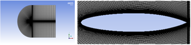
The mesh generation tool in ANSYS software generates a structured C-type mesh. An inflation layer is added near the boundary of the airfoil for more accurate computation procedure.
The grid's top and lower bounds are 12 chords apart from the airfoil profile, and it stretches from 20 chords downstream to 12 chords upstream.
A set of edge sizing, face meshing and transition layer is applied for generating the mesh. The generated grid has 52800 elements and 53240 nodes. Pressure far-field and pressure outlet boundary condition are selected in specific named selection zones. For the airfoil walls, no-slip boundary condition is considered.
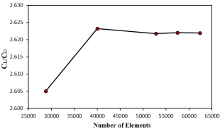
2.4. Mesh Independency Test
Grid independency test is done by increasing the number of elements. Elements number is controlled by edge sizing. Lift to Drag Ratio CL/CD is considered as grid independency parameter.
Figure 2. Variation of CL/CD with the number of elements at α=20° and M=1.1.
Mesh dependency test is done for 20° angle of attack and at Mach 1.1. Lift to Drag Ratio CL/CD is compared against the total no of mesh elements. Figure 2 demonstrate that, given acceptable mesh quality, the lift to drag ratio CL/CD stay constant after 52800 elements. So, in order to minimize the complexity with minimum cost and time 52800 elements was chosen for this current study.
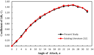
2.5. Model Validation
For the validation purpose outcome from the present study is compared with the existing literature of Ebrahim Hosseini
[12]
E. Hosseini, “CFD analysis of the aerodynamic characteristics of biconvex airfoil at compressible and high Mach numbers flow,” SN Appl. Sci., vol. 1, no. 10, p. 1283, Oct. 2019,
. Figure 3 shows the comparison of coefficient of lift (CL) between present study and existing literature. For Mach no 1.2 validation was done. The red curve indicates the CL values from the existing literature
[12]
E. Hosseini, “CFD analysis of the aerodynamic characteristics of biconvex airfoil at compressible and high Mach numbers flow,” SN Appl. Sci., vol. 1, no. 10, p. 1283, Oct. 2019,
and the black curve indicates the values of CL from this present study. Both of the CL values are plotted against the angle of attack (α). These curves show similar pattern and provide almost the same values.
Figure 3. Comparison of CL between present study and existing literature
[12]
E. Hosseini, “CFD analysis of the aerodynamic characteristics of biconvex airfoil at compressible and high Mach numbers flow,” SN Appl. Sci., vol. 1, no. 10, p. 1283, Oct. 2019,
Figure 3 shows that CL values obtained in this present study are in a good agreement with the existing literature
[12]
E. Hosseini, “CFD analysis of the aerodynamic characteristics of biconvex airfoil at compressible and high Mach numbers flow,” SN Appl. Sci., vol. 1, no. 10, p. 1283, Oct. 2019,
. Though there are some discrepancies due to the differences in boundary conditions, this can be ignored. As numerical results had a good agreement with the existing results, it can be said that the current study is on the right track.
3. Results and Discussion
3.1. Variation of Aerodynamic Characteristics with Different Mach Numbers
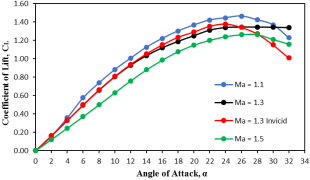
The lift coefficient's variation with changes in the angle of attack is seen in the Figure 4. As the angle of attack increases, the lift coefficient rises, but as the Mach number increases, it falls. The lift coefficient abruptly decreases when the angle of attack increases beyond a particular point. We call this stall situation.
From Figure 4 it is seen that, stall angle for Mach no 1.1, 1.3, 1.3 (inviscid) and 1.5 are 26°, 28°,24° and 28° respectively. For the viscous model, the stall angle of attack did not rise as Mach rose. The precise angle can be established by raising the angle of attack by a little amount. This angle at which stall occurs is very important for airfoil design. If angle of attack increased beyond this value, lift coefficient will reduce drastically hence fatal accident will occurs.
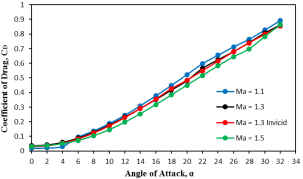
Figure 5. Drag coefficient variations with varying Mach numbers.
From Figure 5, it is clear that the drag coefficient increases with the increase of angle of attack but dropped with increasing Mach number. After stall drag coefficient still increasing. At stall, the total force is pointing backwards as a result drag coefficient increased.
The lift-to-drag ratio, also known as airfoil efficiency, shown by Figure 6, shows how well an airfoil generates lift in relation to the drag it generates. By increasing angle of attack from 0°, airfoil efficiency is also increasing. The peak efficiency is observed at an angle of attack below 10°. Specifically, for Ma =1.1, the maximum efficiency occurs at an angle of attack of 4°. For Ma = 1.3 and 1.5 maximum efficiency occurs at 6° angle of attack. The maximum efficiency for the inviscid model is achieved at an angle of attack of 4°.
Figure 6. Changes of lift to drag ratio with different Mach number.
3.2. Pressure Contours at Different Mach Numbers
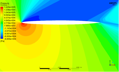
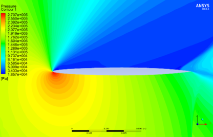
Pressure distribution around airfoil provides proper idea about lift generation. Generally, pressure on lower surface of airfoil is larger than upper surface. Due to this unequal pressure force airfoil gains a net upward force which known as lift force. For supersonic flow, shock wave and expansion waves are formed. Pressure contours of biconvex airfoil for different Mach numbers are given below.
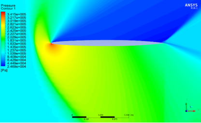
Figure 9. Pressure contour for Mach number 1.5 (α=18°).
In the above pressure contours, color graphic shows magnitude of pressure in Pa unit. Pressure around the airfoil is of main interest. Pressure in the upper surface of airfoil is lower than the lower surface. Due to lower pressure in upper surface, airfoil generates lift. From pressure contours shown by Figure 7 to Figure 9, it is clearly seen that both shock waves and expansion waves are formed in all of the pressure contours. The zone of silence which is the zone outside the oblique shock in the upper surface is represented by the blue color in the pressure contours. Bow shock waves form close to the airfoil's leading edge. Additionally, oblique shock waves can be seen at the airfoil's trailing edge. Behind the oblique shock wave the pressure is dropped which is also visible in the pressure contours.
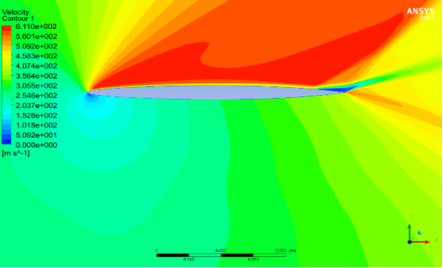
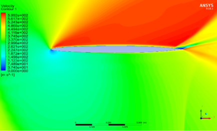
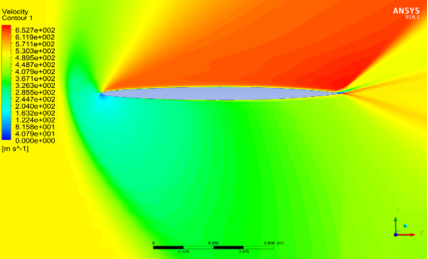
3.3. Velocity Contours at Different Mach Numbers
The velocity contours for various flows with varying Mach numbers are displayed in Figures 10 through 12. The velocity differential between the upper and lower surfaces is negligible for angle of attack close to zero. After increasing angle of attack, velocity difference increases. In velocity contours, red zone indicates higher velocity and blue zone indicates lower velocity. The magnitude of velocity is maximum within the zone of silence. This difference can be described by Bernoulli law. According to Bernoulli, total energy of a moving fluid will be constant. From pressure contour, it is found that pressure at lower surface is higher than upper surface. So, velocity at upper surface must be larger than lower surface which is seen in velocity contours. By increasing velocity, flow separation point is moved downstream. Flow separation point is identified by blue color in velocity contour. Velocity contour indicates that, flow separation in upper surface is moved downstream as the Mach no of flows increased. Flow separation started from the rear stagnation point. At this point fluid velocity is zero shown by the bluish zone in the upper surface.
Figure 12. Velocity contour for Mach number 1.5 (α=18°).
4. Conclusions
The aerodynamic properties of a biconvex aerofoil in supersonic flow are examined in this work. Two dimensional, steady state, compressible flow simulation is carried out using ANSYS CFD packages. The results showed that while the lift coefficient and lift to drag ratio fall as the Mach number increases, the drag coefficient increases. Stall angle found for Mach number 1.1, 1.3 and 1.5 for viscid flow are 26°, 28 and 28° respectively. Stall angle increased from 26° to 28° as the Mach number increased from Ma=1.1 to 1.5. Flow separation occurs after the stall condition. As a result, the flow separation is also delayed by raising the Mach number. At Ma = 1.1, the biconvex airfoil exhibits the highest lift and drag coefficient values and maximum aerodynamic efficiency.
Abbreviations
Ma
Mach Number
CL
Coefficient of Lift
CD
Coefficient of Drag
CL/CD
Lift to Drag Ratio
α
Angle of Attack
Acknowledgments
The authors gratefully acknowledge the support of the Department of Mechanical Engineering, Khulna University of Engineering and Technology, Khulna, Bangladesh, in completing this work successfully.
Authors Contributions
Deboprio Biswas: Conceptualization, Data curation, Formal Analysis, Methodology, Validation, Visualization, Writing – original draft
J. D. Anderson, Fundamentals of aerodynamics, Fifth Edition in SI Units. New York: McGraw-Hill Education, 2011.
[2]
A. Bose and V. K. Viswanathan, “Mitigating the Piston Effect in High-Speed Hyperloop Transportation: A Study on the Use of Aerofoils,” Energies, vol. 14, no. 2, p. 464, Jan. 2021,
E. L. Houghton and P. W. Carpenter, Aerodynamics for engineering students, 5. ed., Reprinted. Amsterdam: Elsevier, Butterworth-Heinemann, 2008.
[5]
S. Askari, M. H. Shojaeefard, and K. Goudarzi, “Numerical and analytical solution of compressible flow over double wedge and biconvex airfoils,” Engineering Computations, vol. 28, no. 4, pp. 441–471, May 2011,
Md. Abdul Hamid, A. B. M. Toufique Hasan, S. M. Alimuzzaman, S. Matsuo, and T. Setoguchi, “Compressible flow characteristics around a biconvex arc airfoil in a channel,” Propulsion and Power Research, vol. 3, no. 1, pp. 29–40, Mar. 2014,
S Athul Krishna and MR Aswin, “Comparative study over double wedge and biconvex airfoils for laminar flow using CFD,” Journal of Physics, Coimbatore, India, Oct. 2022.
[8]
L. M. Shaw, D. R. Boldman, A. E. Buggele, and D. H. Buffum, “Unsteady Pressure Measurements on a Biconvex Airfoil in a Transonic Oscillating Cascade,” Journal of Engineering for Gas Turbines and Power, vol. 108, no. 1, pp. 53–59, Jan. 1986,
H. Zhou, G. Wang, and Z. Liu, “Numerical analysis on flutter of Busemann-type supersonic biplane airfoil,” Journal of Fluids and Structures, vol. 92, p. 102788, Jan. 2020,
R. K. Bansal, A Textbook of Fluid Mechanics and Hydraulic Machines. New Delhi: Laxmi Publications, 2017.
[11]
Mikhail Pavlovich Bulat and Pavel Victorovich Bulat, “Comparison of Turbulence Models in the Calculation of Supersonic Separated Flows,” World App. Sciences Journal, vol. 27, no. 10, pp. 1263–1266, 2013,
E. Hosseini, “CFD analysis of the aerodynamic characteristics of biconvex airfoil at compressible and high Mach numbers flow,” SN Appl. Sci., vol. 1, no. 10, p. 1283, Oct. 2019,
Biswas, D., Mustak, R., Bakchi, S., Biswas, S. (2025). Influence of Mach Number on the Aerodynamic Performance of a Biconvex Airfoil. Engineering and Applied Sciences, 10(2), 11-17. https://doi.org/10.11648/j.eas.20251002.11
Biswas, D.; Mustak, R.; Bakchi, S.; Biswas, S. Influence of Mach Number on the Aerodynamic Performance of a Biconvex Airfoil. Eng. Appl. Sci.2025, 10(2), 11-17. doi: 10.11648/j.eas.20251002.11
Biswas D, Mustak R, Bakchi S, Biswas S. Influence of Mach Number on the Aerodynamic Performance of a Biconvex Airfoil. Eng Appl Sci. 2025;10(2):11-17. doi: 10.11648/j.eas.20251002.11
@article{10.11648/j.eas.20251002.11,
  author = {Deboprio Biswas and Rubiat Mustak and Smaran Bakchi and Sukanto Biswas},
  title = {Influence of Mach Number on the Aerodynamic Performance of a Biconvex Airfoil
},
  journal = {Engineering and Applied Sciences},
  volume = {10},
  number = {2},
  pages = {11-17},
  doi = {10.11648/j.eas.20251002.11},
  url = {https://doi.org/10.11648/j.eas.20251002.11},
  eprint = {https://article.sciencepublishinggroup.com/pdf/10.11648.j.eas.20251002.11},
  abstract = {This study concentrated on numerically simulating the behavior of a biconvex airfoil under compressible flow conditions. A turbulent, two-dimensional, compressible steady flow is considered. The study entails examining the biconvex airfoil's aerodynamic properties as the Mach number increases. The flow turbulence was predicted by the simulations using the SST k-ω viscous modelling and Reynolds-averaged Navier-Stokes equations. Under turbulent and steady-state flow conditions, simulations were done using commercial ANSYS FLUENT software. Both viscid and inviscid flows were considered. Validation is done with the help of existing literature. Mesh independency test is done. Visualization is also done to understand the flow conditions clearly. The simulations were done for Mach number 1.1, 1.3 and 1.5. According to the findings, the coefficient of lift rises as the angle of attack increases but falls as the Mach number increases. The delay of boundary layer separation causes the flow separation to lag as the Mach number rises. As the angle of attack increases, the coefficient of drag also rises. For both viscid and inviscid flows, the stall angle changes from 24° to 28° as the Mach number rises from Ma=1.1 to 1.5. The airfoil shows maximum aerodynamic performance at Ma = 1.1 with the highest magnitude of coefficient of lift.
},
 year = {2025}
}
TY  - JOUR
T1  - Influence of Mach Number on the Aerodynamic Performance of a Biconvex Airfoil

AU  - Deboprio Biswas
AU  - Rubiat Mustak
AU  - Smaran Bakchi
AU  - Sukanto Biswas
Y1  - 2025/03/07
PY  - 2025
N1  - https://doi.org/10.11648/j.eas.20251002.11
DO  - 10.11648/j.eas.20251002.11
T2  - Engineering and Applied Sciences
JF  - Engineering and Applied Sciences
JO  - Engineering and Applied Sciences
SP  - 11
EP  - 17
PB  - Science Publishing Group
SN  - 2575-1468
UR  - https://doi.org/10.11648/j.eas.20251002.11
AB  - This study concentrated on numerically simulating the behavior of a biconvex airfoil under compressible flow conditions. A turbulent, two-dimensional, compressible steady flow is considered. The study entails examining the biconvex airfoil's aerodynamic properties as the Mach number increases. The flow turbulence was predicted by the simulations using the SST k-ω viscous modelling and Reynolds-averaged Navier-Stokes equations. Under turbulent and steady-state flow conditions, simulations were done using commercial ANSYS FLUENT software. Both viscid and inviscid flows were considered. Validation is done with the help of existing literature. Mesh independency test is done. Visualization is also done to understand the flow conditions clearly. The simulations were done for Mach number 1.1, 1.3 and 1.5. According to the findings, the coefficient of lift rises as the angle of attack increases but falls as the Mach number increases. The delay of boundary layer separation causes the flow separation to lag as the Mach number rises. As the angle of attack increases, the coefficient of drag also rises. For both viscid and inviscid flows, the stall angle changes from 24° to 28° as the Mach number rises from Ma=1.1 to 1.5. The airfoil shows maximum aerodynamic performance at Ma = 1.1 with the highest magnitude of coefficient of lift.

VL  - 10
IS  - 2
ER  -