Research/Technical Note | | Peer-Reviewed

Numerical Investigation of Shallow Tunnel Settlement Using the Finite Element Software Plaxis 2D

Received: 17 January 2025     Accepted: 2 July 2025     Published: 19 July 2025
Views:       Downloads:
Abstract

Shallow tunnels are often subject to settlement, which can compromise the performance and safety of underground structures. This is especially relevant for developing cities that need to construct tunnels for transportation infrastructure projects. This study examines the settlement behavior of shallow tunnels through numerical simulations using the finite element program Plaxis 2D. The study investigates the impact of various factors, including stress magnitude, rock type, tunnel depth, soil layer thickness, and tunnel liner thickness, on the settlement behavior of shallow tunnels. The study also guides the choice of the appropriate tunnel structure for geotechnical practice. The results indicate that different soil and rock types exhibit distinct settlement patterns under both vertical and horizontal deformations. For instance, hard rock has less settlement than weak and medium rock, and deep sand has less deformation than sand and clay. The results also indicate that tunnel liner, load distribution area width, and tunnel type are sensitive parameters that influence tunnel settlement. This study contributes to the understanding of factors that affect tunnel settlement, providing valuable insights for future tunnel design and construction. The findings of this study can help improve the stability and safety of shallow tunnels, as well as assist in developing more accurate settlement prediction models.

Published in International Journal of Engineering Management (Volume 9, Issue 2)
DOI 10.11648/j.ijem.20250902.11
Page(s) 50-58
Creative Commons

This is an Open Access article, distributed under the terms of the Creative Commons Attribution 4.0 International License (http://creativecommons.org/licenses/by/4.0/), which permits unrestricted use, distribution and reproduction in any medium or format, provided the original work is properly cited.

Copyright

Copyright © The Author(s), 2025. Published by Science Publishing Group

Keywords

Numerical Simulations, Parametric Study, Shallow Tunnels, Settlement

1. Introduction
Many developing cities are experiencing rapid urbanization, which in turn increases the demand for transportation. To address this challenge, new metro routes, tracks, and rail transit systems are being constructed, which necessitates tunnel excavation. These tunnels facilitate efficient and reliable traffic flow in urban areas. Addis Ababa is one of the African cities that faces the need for modern urban mobility systems, as its public transport service is insufficient. Currently, most of the city's transportation relies on automobiles.
Compared with deep tunnels, shallow tunnels may induce greater strata deformations and ground surface settlements, seriously affecting the safety of tunnel constructions and surroundings. Differential settlement can cause structural damage, groundwater infiltration, and track distortion, significantly impacting the maintenance cost and safety of metro systems . Understanding the mechanism of large-scale and long-lasting tunnel settlement is essential.
Numerous studies have documented short-term tunnel settlement during construction . Conversely, studies on long-term tunnel settlement after construction are relatively limited. The surface settlement caused by shield construction of double-line tunnels in mudstone areas is influenced by various parameters, which makes it difficult to predict and control. One of the methods to analyze surface settlement is Peck’s equation . However, this method may not apply to all cases. For example, Sunwangawat et al proposed an empirical equation based on the surface settlement data of double-line shield construction in a clay layer in Bangkok. They found that the tunneling pressure, grouting pressure, and other shield construction parameters had significant effects on the settlement range and maximum settlement. Similarly, Zheng used an empirical equation to analyze the surface settlement of the Changchun Metro Line 1, which was constructed through clay and mudstone layers.
Empirical equations have some limitations in analyzing the surface settlement of double-line tunnels in mudstone areas. They are usually specific to certain locations, require sufficiently accurate measurement data, and must be calibrated against local measurements. Numerous factors influence surface settlement during the shield construction of double-line tunnels, and it varies significantly. Therefore, other methods have been proposed by scholars to study surface settlement, such as analytical methods , model tests , and numerical simulations .
The surface settlement caused by metro tunnel construction is a complex phenomenon that depends on various factors, including groundwater level, tunnel depth, section characteristics, construction methods, soil properties, and tunnel type. Several studies have employed numerical simulations to examine the impact of these factors on tunnel deformation and surface settlement . For example, Liu and Wang performed a 3D finite element analysis of a section of the Guangzhou metro and compared the results with the monitoring data. Bai and Xue et al. examined the influence of different surrounding rock properties and concluded that weak rocks and significant ground stress were the main reasons for larger deformation. The authors investigated how tunnel deformation in soft soils depends on factors such as burial depth, lining thickness, and section size . The accuracy of the numerical calculation could be enhanced by taking into account the relaxation of surrounding rocks, which was estimated to be 30-35% by the . Liu et al. suggested that increasing the grouting pressure in shield construction could reduce the deformation of surrounding rocks.
This paper mainly discusses the evaluation trend of rock deformation during tunnel construction in soil and rock. Numerical analysis of tunnel settlement using Plaxis 2D software is conducted to investigate the effects of various parameters, including magnitude of stress, tunnel depth, tunnel lining thickness, tunnel type, upper clay thickness, load distribution, and upper layer soil type. The purpose of this research is to provide valuable insights into the design and performance of tunnel systems, thereby enhancing the quality and reliability of geological and geotechnical engineering practices.
2. Materials and Methods
Plaxis 2D finite element software was used to conduct plane strain analyses. The model boundaries were extended sufficiently to eliminate boundary effects. A model size of 100 × 50 m (X-Y axis) was used. Horizontal movement along the vertical boundaries and horizontal and vertical movements along the base were restrained. Ground surface loadings were not considered in this model. A total of 1242 fifteen-node triangular elements were used to mesh the subsoil and structural materials, as shown in Figure 1. The types of rock and soil in the study area are represented in Tables 1 and 2. These parameters were used as inputs for the modeling process while keeping other factors constant. The aim was to examine the effect of each parameter on the model's outcome.
Table 1. Material properties of rock types.

Parameter

Symbol

Weak rock

Medium rock

Hard rock

Unit

Coefficient of sliding friction

µ

0.3

0.28

0.21

-

Angle of internal friction

φ

30

35

39

[o]

Unit weight

ɣ

26.5

27.5

28

kN/m3

Cohesion

Cref

10000

15000

20000

kN/m2

Young modulus

E’

Poisson’s ratio

ν’

0.25

0.28

0.30

-

Table 2. Material properties of soil types.

Parameter

Symbol

Clay

Sand

Deep sand

Unit

Soil unit weight

ɣ

18

20

21

kN/m3

Young’s modulus at reference level

E’

400

550

600

kN/m2

Friction angle

φ

30

31

35

[o]

Poisson’s ratio

ν’

0.33

0.3

0.3

-

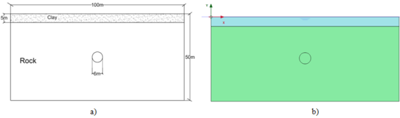
Figure 1. Geometry of the tunnel (a) and boundaries (b).
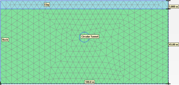
2.1. Constitutive Model
Plaxis 2D was used to represent the rock masses with a linear elastic-perfectly plastic Mohr-Coulomb constitutive model. More advanced rock constitutive models, such as strain-softening, can capture the nonlinear stress-strain behavior of rock masses more accurately. Still, they also require several model parameters to be input. Therefore, the Mohr-Coulomb model was deemed adequate for this study, as it is a conventional method for representing the failure of soils and rocks . The Mohr-Coulomb model requires cohesion, angle of internal friction, bulk modulus, and shear modulus as input parameters. The model requires five parameters to represent the mechanical behavior of the soil and rock: E, v, c, ϕ, and ψ. These are the elasticity modulus, Poisson’s ratio, cohesion, internal friction angle, and dilatancy angle, respectively. These parameters help to evaluate the soil and rock characteristics .
The following equation can express the Mohr-Coulomb model.
τ=c-σ tanφ(1)
In Equation (1), τ is the shear stress, σ is the normal stress, c is the soil material and φ is the angle of internal friction.
2.2. Boundary Condition
Tunnel depth and radius determined the boundary conditions for the finite element model. A tunnel is considered shallow if the ratio of depth to radius is less than or equal to 25. In this study, the tunnel had a depth of 50 m and a radius of 3 m, resulting in a ratio of less than 25. Therefore, the tunnel was considered shallow, and fixed boundary conditions were applied on all sides of the model. Once boundary conditions were defined, the model was meshed.
2.3. Meshing Generation
Mesh generation is an essential step in finite element analysis, as it divides the geometry into elements that can be solved numerically. In this study, the components illustrated in Figure 2 were constructed using a mesh of 15-node triangular elements that was automatically generated in Plaxis 2D, with refinements in areas of concentrated stress and settlement, such as the tunnel location. This approach ensured that the mesh was sufficiently dense to capture the system complex behavior while also being efficient enough to solve problems within the available computational resources.
3. Results and Discussion
3.1. Influence of the Magnitude of Stress on Tunnel Settlement
This study examined the effect of stress magnitude on the deformation of tunnels in medium rock using numerical simulations. Considering five different stress magnitudes: 100 MPa, 200 MPa, 300 MPa, 400 MPa, and 500 MPa, by measuring the vertical displacement, horizontal displacement, and total displacement of the tunnel cross-section under different stress levels. The result in Figure 3 illustrates the relationship between stress magnitude and tunnel deformation. As shown in the figure, the deformation of the tunnel increases with increasing stress magnitude. Increasing the stress magnitude five times results in tunnel settlement on the vertical side at 23% and on the horizontal side at 20%. This suggests that a higher stress level results in greater strain and damage to the tunnel structure. Therefore, it is better to consider reducing the stress magnitude, soil reinforcement, or grouting to decrease the deformation of tunnels in medium and soft rock .
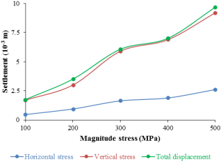
Figure 3. Effect of different stress magnitudes on tunnel settlement.
3.2. Influence of Tunnel Location Below Ground Level on Tunnel Settlement
Tunnel settling is greatly influenced by the depth of the tunnel below the earth. This section aims to identify the most stable tunnel depth. Four locations, including the reference point, were considered to examine the effect of depth. The overburden depth above the tunnel ranged from 10 m to 25 m in 5 m increments, and the analysis results are shown in Figure 4.
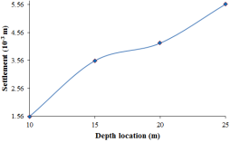
Figure 4. Effect of different tunnel depth locations on tunnel settlement.
The overburden, or the amount of rock above the tunnel, is determined by the tunnel's depth. The tunnel faces pressure from the overburden, and deeper tunnels typically experience greater overburden pressures. As the rock fills the void left by excavation, the increasing pressure causes more settling. Figure 5 illustrates that tunnel settlement increases with depth. Doubling the tunnel depth by 50% results in a 43% increase in settlement. The stability of the tunnel improves as it approaches the ground surface.
3.3. Influence of the Thickness of the Liner on Tunnel Settlement
The stability of tunnels in medium rock depends on the liner thickness, which acts as a protective layer to prevent water ingress and rock collapse. This study investigated the impact of liner thickness on tunnel deformation in medium rock using numerical simulations. It tested five different liner thicknesses: 0.1, 0.2, 0.3, 0.4, and 0.5 meters, measuring the vertical, horizontal, and total displacements of the tunnel cross-section under various loading conditions. The results are shown in Figure 5, which displays the relationship between liner thickness and tunnel deformation. As shown in the figure, tunnel deformation increases as liner thickness decreases. A liner thickness of 0.1 meters results in a settlement of 5.2×10⁻³ meters, which is 80% greater than the 4.1×10⁻³ meters settlement observed at 0.2 meters thickness.
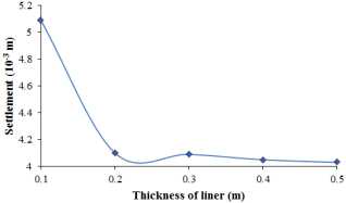
Figure 5. Effect of different-thickness liners on tunnel settlement.
This is because a thicker tunnel liner distributes the weight of the surrounding dirt more evenly and is better able to withstand pressure, reducing the chance of settling. Additionally, a thicker liner is stiffer, which helps prevent deformations and manage settling. By making the tunnel construction and surrounding ground less vulnerable to external stresses, the increased stiffness minimizes settling.
3.4. Influence of Type of Tunnel
Settlement can be significantly affected by the type of tunnel. In this study, we compare the deformation behavior of two tunnel types: the New Austrian Tunneling Method (NATM) tunnel and a bored tunnel. The New Austrian Tunneling Method (NATM) is a modern approach to tunnel design and construction that employs advanced monitoring to optimize different wall reinforcement techniques based on the rock type encountered. In contrast, a bored tunnel, which minimizes ground disturbance, is constructed in situ without removing the surrounding earth. These tunnels typically have a horseshoe-shaped or circular cross-section. As a result, they generally cause less settling compared to cut-and-cover tunnels.
The study applies these tunnels in medium- to hard-rock formations. It measures the horizontal and vertical deformations of both tunnels and analyzes how their differences affect tunnel stability. Finding that the bored tunnel has higher deformation values than the NATM tunnel in both directions indicates that the NATM tunnel is more resistant to deformation. The lowest deformation value for the NATM tunnel is 1.17×10⁻³ m in the horizontal direction and 4.27×10⁻³ m in the vertical direction. In contrast, the highest deformation value for the bored tunnel is 1.18×10⁻³ m in the horizontal direction and 4.38×10⁻³ m in the vertical direction. The deformation values vary slightly among the four locations; however, this has a minimal impact on tunnel design and construction in medium rock. We present the graphical results of our simulations in Figure 6 below.
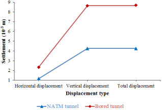
Figure 6. Effect of different tunneling types on tunnel settlement.
3.5. Influence of Thickness of Upper Clay Layer
This study investigates the impact of the upper clay layer's thickness on tunnel deformation in medium rock. The thickness of the upper clay layer ranges from 10 to 25 meters, and deformation is assessed through horizontal, vertical, and total displacements of the tunnel. Figure 7 illustrates the relationship between clay layer thickness and displacement. Greater settlement values occur with a thicker top clay layer due to increased compressibility of the clay. The weight of the tunnel presses down on the clay layer, causing it to settle and deform. Additional clay can lead to more distortion and settlement when the clay layer is thicker.
Therefore, the displacement decreases as the thickness of the upper clay layer increases, indicating that thicker clay layers offer greater resistance to deformation. Additionally, longer settling times occur with a thicker clay layer. Due to its increased thickness, the clay takes more time to fully deform and settle. This delays the settling process and can disrupt nearby infrastructure or constructions.
The maximum deformation occurs at 10 m thickness, with horizontal and vertical displacements of 2.32×10⁻³ m and 1.0×10⁻² m, respectively. The minimum deformation occurs at 25 m thickness, with horizontal and vertical displacements of 0.261×10⁻³ m and 1.41×10⁻³ m, respectively. The range of horizontal displacement is 2.059×10⁻³ m, while the range of vertical displacement is 8.59×10⁻³ m. The total displacement of the tunnel exceeds 57% of the initial tunnel settlement when the upper clay layer thickness increases by 5 m, indicating that vertical deformation is more sensitive to changes in the upper clay layer thickness than horizontal deformation.
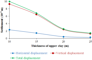
Figure 7. Effect of clay layer thicknesses on tunnel settlement.
3.6. Influence of Load Distribution of Area Width
Tunnel settlement is also affected by the width of the excavation area or tunnel entrance. This study examines how the width of the load distribution area impacts tunnel deformation in medium rock. The load distribution area width ranges from 10 to 50 meters, and the total displacement of the tunnel is measured to assess deformation. Figure 8 illustrates the relationship between load distribution area width and total displacement. The total displacement increases as the load distribution area width increases, indicating that the tunnel undergoes greater deformation under larger loads.
Larger zones of influence, where ground changes and settlement are more noticeable, generally originate from wider regions. Conversely, smaller areas experience less settlement because the surrounding ground is disturbed less. Increasing the distribution area by 10 meters led to an 82% increase in settlement. Therefore, the study concludes that the width of the load distribution area is an essential factor influencing tunnel deformation in medium rock.
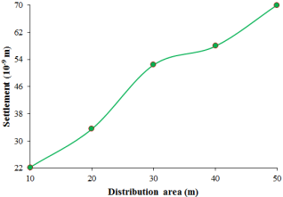
Figure 8. Effect of different load distribution areas on tunnel settlement.
3.7. Influence of Diameter of Tunnel
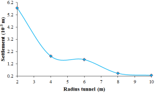
Figure 9. Effect of different tunnel diameters on tunnel settlement.
This study examines the impact of tunnel diameter on deformation in medium rock. The analyzed tunnel diameters are 2, 4, 6, 8, and 10 meters, with other parameters held constant. Deformation is assessed by measuring the total displacement of the tunnel. A void area forms when the earth around a tunnel is disturbed during the excavation process. Settlement occurs as the rock or soil above adjusts to the changed conditions, and larger settlements happen with increased space created by larger tunnel diameters.
Figure 9 shows the relationship between tunnel diameter and total displacement. As seen, the total displacement decreased by 37% as the tunnel radius increased to 2 m, indicating that larger tunnels tend to be more stable than smaller ones. Therefore, the tunnel diameter is an essential factor influencing tunnel deformation in medium rock. The overall impact of tunnel diameter on settlement results from a complex interaction of several variables, including geotechnical considerations, construction methods, and ground conditions.
3.8. Influence of Upper-layer Soil Types
This study examines the impact of upper-layer soil type on tunnel deformation in medium rock. The analyzed soil types include sand, deep sand, and clay. The total displacement of the tunnel indicates the degree of deformation. Figure 10 compares the total displacement for different soil types. Deep sand experiences the least deformation, followed by sand and clay. This is because deep sand has a higher modulus of elasticity, unit weight, and angle of friction than the other soils. Therefore, we conclude that the soil type in the upper layer is a key factor influencing tunnel deformation in medium- to high-strength rock.
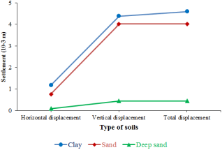
Figure 10. Effect of different soil layers on tunnel settlement.
3.9. Influence of the Below-layer Rock Type
This study examines the impact of rock type on tunnel deformation. We categorize the rocks into three types: weak, medium, and hard. The research assesses how variations in the coefficient of sliding friction impact the vertical, horizontal, and total displacements of the tunnel. Results show that displacements decrease as the coefficient of friction rises, indicating that harder rocks cause less tunnel deformation. Figure 11 below displays the study findings. For instance, on weak rock with a sliding friction coefficient of 0.3, the maximum horizontal deformation is 1.37×10⁻³ m, and the maximum vertical deformation is 5.05×10⁻³ m. Conversely, on hard rock with a coefficient of 0.6, the minimum horizontal deformation is 1.12×10⁻³ m, and the minimum vertical deformation is 4.15×10⁻³ m.
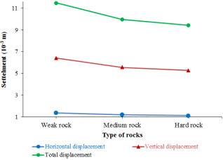
Figure 11. Effect of different rock types on tunnel settlement.
4. Conclusions
Tunnel settlement analysis is an essential part of geotechnical engineering because it greatly affects the safety and performance of the tunnel structure. In conclusion, the study utilized Plaxis 2D, a finite element software specifically designed for geotechnical applications, to investigate the tunnel's settlement under various conditions.
a. The type of rock significantly influences tunnel deformation because it determines the stability and resistance of the rock mass against external forces. As the rock becomes harder, deformation tends to decrease, which impacts tunnel stability. However, when stress levels increase, deformation also rises due to the combined elastic and plastic responses of the rock mass. Therefore, it is essential to assess stress levels and their effects on tunnel deformation both before and during construction.
b. The location and parameters of a tunnel greatly influence its deformation, as deeper tunnels tend to cause more deformation due to increased confining pressure and temperature. Therefore, it is essential to consider these factors when planning and constructing tunnels. The thickness of the tunnel liner also impacts deformation, as thicker liners better resist external loads and reduce deformation. Thus, optimizing the liner thickness based on expected deformation and load conditions is essential.
c. The study compared two types of tunnels: Bored and NATM tunnels. NATM tunnels exhibit greater resistance to deformation due to the inherent strength of the surrounding rock mass, whereas bored tunnels require mechanical excavators and concrete linings. The thickness of the upper clay layer also influences tunnel construction. A thicker layer helps reduce deformation and stress, which is beneficial for tunnels in soft soil conditions. Therefore, choosing the right tunnel type depends on geological and geotechnical conditions.
d. The deformation of a tunnel is affected by three parameters: the width of the load distribution area, the tunnel's radius, and the upper soil layer. The width parameter increases as the load distribution area expands, resulting in greater deformation. Conversely, the tunnel's radius decreases as the radius itself grows, due to reduced curvature and lower bending stress in the tunnel lining.
e. The study compared three upper-layer soil types: clay, sand, and deep sand. The results indicated that tunnel deformation decreases in clay due to its higher cohesion and lower permeability, while sand offers greater stability and resistance. Therefore, it is essential to consider these factors when designing and constructing tunnels in various soil conditions.
The study focused on the static analysis of tunnel parameters, suggesting that future research should explore dynamic analysis to evaluate blasting effects on tunnel structures. Improving tunnel system sensitivity by adjusting bolt lengths, bond strength, and testing support systems such as shotcrete and steel sets could yield design guidelines, thereby enhancing safety and performance in tunnel construction.
Abbreviations

NATM

New Austrian Tunneling Method

Acknowledgments
The authors appreciate the support of the Department of Civil Engineering at Ambo University, which provided the essential material and resources to accomplish this study goals.
Data Availability
Data will be made available on request from the corresponding author.
Funding
No funds, grants, or other support were received.
Conflicts of Interest
The authors declare no conflicts of interest.
References
[1] Wang Z, Wang L, Li L, Wang J (2014) Failure mechanism of tunnel lining joints and bolts with uneven longitudinal ground settlement. Tunn Undergr Sp Technol 40: 300-308.
[2] Huang X, Huang H, Zhang J (2012) Flattening of jointed shield-driven tunnel induced by longitudinal differential settlements. Tunn Undergr Sp Technol 31: 20-32.
[3] Gong W, Juang CH, Huang H, et al (2015) Improved analytical model for circumferential behavior of jointed shield tunnels considering the longitudinal differential settlement. Tunn Undergr Sp Technol 45: 153-165.
[4] Di H, Zhou S, Xiao J, et al (2016) Investigation of the long-term settlement of a cut-and-cover metro tunnel in a soft deposit. Eng Geol 204: 33-40.
[5] Zhou S, Ji C (2014) Tunnel segment uplift model of earth pressure balance shield in soft soils during subway tunnel construction. Int J Rail Transp 2: 221-238.
[6] Yuan C, Zhang M, Ji S, et al (2022) Analysis of factors influencing surface settlement during shield construction of a double-line tunnel in a mudstone area. Sci Rep 12: 1-20.
[7] Jin H, Yuan D, Zhou S, Zhao D (2022) Short-Term and Long-Term Displacement of Surface and Shield Tunnel in Soft Soil: Field Observations and Numerical Modeling. Appl Sci 12.
[8] Peck RB (1969) Deep excavation and tunnelling in soft ground. Proceed. 7th Int Conf soil Mech Found Eng 225-290.
[9] Suwansawat S, Einstein HH (2007) Describing Settlement Troughs over Twin Tunnels Using a Superposition Technique. J Geotech Geoenvironmental Eng 133: 445-468.
[10] Li J, Liu A, Xing H (2023) Study on Ground Settlement Patterns and Prediction Methods in Super-Large-Diameter Shield Tunnels Constructed in Composite Strata. Appl Sci 13.
[11] Kessler FB (2018) F Ostering I O T S Olutions for S Ustainable. 127: 36-37.
[12] Park KH (2004) Elastic Solution for Tunneling-Induced Ground Movements in Clays. Int J Geomech 4: 310-318.
[13] Kim SH, Burd HJ, Milligan GWE (1998) Model testing of closely spaced tunnels in clay. Geotechnique 48: 375-388.
[14] Marshall AM, Klar A, Mair RJ (2010) Tunneling beneath Buried Pipes: View of Soil Strain and Its Effect on Pipeline Behavior. J Geotech Geoenvironmental Eng 136: 1664-1672.
[15] Yang C, Hu Z, Huang D, Guo F (2020) Failure Mechanism of Primary Support for a Shallow and Asymmetrically Loaded Tunnel Portal and Treatment Measures. J Perform Constr Facil 34.
[16] Lambrughi A, Medina Rodríguez L, Castellanza R (2012) Development and validation of a 3D numerical model for TBM-EPB mechanised excavations. Comput Geotech 40: 97-113.
[17] Liu J, Qi T, Wu Z (2012) Analysis of ground movement due to metro station driven with enlarging shield tunnels under building and its parameter sensitivity analysis. Tunn Undergr Sp Technol 28: 287-296.
[18] Wang C (2019) Influence of underground geotechnical operation on surface buildings through the shield method. Arab J Geosci 12.
[19] Guo X, Wang Z, Geng P, et al (2021) Ground surface settlement response to subway station construction activities using pile-beam-arch method. Tunn Undergr Sp Technol 108: 103729.
[20] Bai C, Xue Y, Qiu D, et al (2021) Analysis of factors affecting the deformation of soft rock tunnels by data envelopment analysis and a risk assessment model. Tunn Undergr Sp Technol 116: 104111.
[21] Vu MN, Broere W, Bosch J (2015) Effects of cover depth on ground movements induced by shallow tunnelling. Tunn Undergr Sp Technol 50: 499-506.
[22] Bizjak KF, Petkovšek B (2004) Displacement analysis of tunnel support in soft rock around a shallow highway tunnel at Golovec. Eng Geol 75: 89-106.
[23] Liu J, Song J, Zhang Z, Hu N (2017) Influence of the Ground Displacement and Deformation of Soil around a Tunnel Caused by Shield Backfilled Grouting during Construction. J Perform Constr Facil 31: 1-9.
[24] Xing Y, Kulatilake PHSW, Sandbak LA (2016) Rock Mass Stability Investigation Around Tunnels in an Underground Mine in USA. Geotech Geol Eng.
[25] Tian D, Zheng H (2023) The Generalized Mohr-Coulomb Failure Criterion. Appl Sci 13.
[26] Shi C, Cao C, Lei M (2017) An analysis of the ground deformation caused by shield tunnel construction combining an elastic half-space model and stochastic medium theory. KSCE J Civ Eng 21: 1933-1944.
[27] Shen LU (2020) Analysis of Ground Settlement in Metro Tunnel Construction with Shield Tunneling Method. IOP Conf Ser Earth Environ Sci 495.
Cite This Article
  • APA Style

    Jilo, N. Z., Hailemariam, R. D., Teklemedhin, M., Yikal, M., Engidawork, M., et al. (2025). Numerical Investigation of Shallow Tunnel Settlement Using the Finite Element Software Plaxis 2D. International Journal of Engineering Management, 9(2), 50-58. https://doi.org/10.11648/j.ijem.20250902.11

    Copy | Download

    ACS Style

    Jilo, N. Z.; Hailemariam, R. D.; Teklemedhin, M.; Yikal, M.; Engidawork, M., et al. Numerical Investigation of Shallow Tunnel Settlement Using the Finite Element Software Plaxis 2D. Int. J. Eng. Manag. 2025, 9(2), 50-58. doi: 10.11648/j.ijem.20250902.11

    Copy | Download

    AMA Style

    Jilo NZ, Hailemariam RD, Teklemedhin M, Yikal M, Engidawork M, et al. Numerical Investigation of Shallow Tunnel Settlement Using the Finite Element Software Plaxis 2D. Int J Eng Manag. 2025;9(2):50-58. doi: 10.11648/j.ijem.20250902.11

    Copy | Download

  • @article{10.11648/j.ijem.20250902.11,
      author = {Nagessa Zerihun Jilo and Rediet Derieb Hailemariam and Mahlet Teklemedhin and Mekdelawit Yikal and Mahder Engidawork and Kalkidan Kefale Berta and Firaol Fituma Chimdesa and Firanboni Fituma Chimdesa and Simera Teferi and Hirei Mohammed Hussen},
      title = {Numerical Investigation of Shallow Tunnel Settlement Using the Finite Element Software Plaxis 2D
    },
      journal = {International Journal of Engineering Management},
      volume = {9},
      number = {2},
      pages = {50-58},
      doi = {10.11648/j.ijem.20250902.11},
      url = {https://doi.org/10.11648/j.ijem.20250902.11},
      eprint = {https://article.sciencepublishinggroup.com/pdf/10.11648.j.ijem.20250902.11},
      abstract = {Shallow tunnels are often subject to settlement, which can compromise the performance and safety of underground structures. This is especially relevant for developing cities that need to construct tunnels for transportation infrastructure projects. This study examines the settlement behavior of shallow tunnels through numerical simulations using the finite element program Plaxis 2D. The study investigates the impact of various factors, including stress magnitude, rock type, tunnel depth, soil layer thickness, and tunnel liner thickness, on the settlement behavior of shallow tunnels. The study also guides the choice of the appropriate tunnel structure for geotechnical practice. The results indicate that different soil and rock types exhibit distinct settlement patterns under both vertical and horizontal deformations. For instance, hard rock has less settlement than weak and medium rock, and deep sand has less deformation than sand and clay. The results also indicate that tunnel liner, load distribution area width, and tunnel type are sensitive parameters that influence tunnel settlement. This study contributes to the understanding of factors that affect tunnel settlement, providing valuable insights for future tunnel design and construction. The findings of this study can help improve the stability and safety of shallow tunnels, as well as assist in developing more accurate settlement prediction models.},
     year = {2025}
    }
    

    Copy | Download

  • TY  - JOUR
    T1  - Numerical Investigation of Shallow Tunnel Settlement Using the Finite Element Software Plaxis 2D
    
    AU  - Nagessa Zerihun Jilo
    AU  - Rediet Derieb Hailemariam
    AU  - Mahlet Teklemedhin
    AU  - Mekdelawit Yikal
    AU  - Mahder Engidawork
    AU  - Kalkidan Kefale Berta
    AU  - Firaol Fituma Chimdesa
    AU  - Firanboni Fituma Chimdesa
    AU  - Simera Teferi
    AU  - Hirei Mohammed Hussen
    Y1  - 2025/07/19
    PY  - 2025
    N1  - https://doi.org/10.11648/j.ijem.20250902.11
    DO  - 10.11648/j.ijem.20250902.11
    T2  - International Journal of Engineering Management
    JF  - International Journal of Engineering Management
    JO  - International Journal of Engineering Management
    SP  - 50
    EP  - 58
    PB  - Science Publishing Group
    SN  - 2640-1568
    UR  - https://doi.org/10.11648/j.ijem.20250902.11
    AB  - Shallow tunnels are often subject to settlement, which can compromise the performance and safety of underground structures. This is especially relevant for developing cities that need to construct tunnels for transportation infrastructure projects. This study examines the settlement behavior of shallow tunnels through numerical simulations using the finite element program Plaxis 2D. The study investigates the impact of various factors, including stress magnitude, rock type, tunnel depth, soil layer thickness, and tunnel liner thickness, on the settlement behavior of shallow tunnels. The study also guides the choice of the appropriate tunnel structure for geotechnical practice. The results indicate that different soil and rock types exhibit distinct settlement patterns under both vertical and horizontal deformations. For instance, hard rock has less settlement than weak and medium rock, and deep sand has less deformation than sand and clay. The results also indicate that tunnel liner, load distribution area width, and tunnel type are sensitive parameters that influence tunnel settlement. This study contributes to the understanding of factors that affect tunnel settlement, providing valuable insights for future tunnel design and construction. The findings of this study can help improve the stability and safety of shallow tunnels, as well as assist in developing more accurate settlement prediction models.
    VL  - 9
    IS  - 2
    ER  - 

    Copy | Download

Author Information
  • Department of Civil Engineering, College of Engineering, Addis Ababa Science and Technology University, Addis Ababa, Ethiopia

  • Department of Civil Engineering, School of Civil and Environmental Engineering, Ambo University, Ambo, Ethiopia

  • Department of Civil Engineering, School of Civil and Environmental Engineering, Ambo University, Ambo, Ethiopia

  • Department of Civil Engineering, School of Civil and Environmental Engineering, Ambo University, Ambo, Ethiopia

  • Department of Civil Engineering, School of Civil and Environmental Engineering, Ambo University, Ambo, Ethiopia

  • Department of Civil Engineering, College of Engineering, Addis Ababa Science and Technology University, Addis Ababa, Ethiopia

  • Department of Civil Engineering, College of Engineering, Addis Ababa Science and Technology University, Addis Ababa, Ethiopia

  • Department of Civil Engineering, College of Engineering, Addis Ababa Science and Technology University, Addis Ababa, Ethiopia

  • Department of Civil Engineering, School of Civil and Environmental Engineering, Addis Ababa University, Addis Ababa, Ethiopia

  • Department of Civil Engineering, School of Civil and Environmental Engineering, Institute of Technology, Dire Dawa University, Dire Dawa, Ethiopia

  • Abstract
  • Keywords
  • Document Sections

    1. 1. Introduction
    2. 2. Materials and Methods
    3. 3. Results and Discussion
    4. 4. Conclusions
    Show Full Outline
  • Abbreviations
  • Acknowledgments
  • Data Availability
  • Funding
  • Conflicts of Interest
  • References
  • Cite This Article
  • Author Information