This paper presents a few relatively simple and transparent methods of material selection for a civil engineering structure in view of sustainability. It is addressed to practicing engineers, designers, production managers, other professionals and students intending to take account of sustainability when choosing the material for new structures or maintaining the existing structures. The presented methods are illustrated by a case study for a navigation lock gate. The materials that are currently applicable for this structure are: structural steel, stainless steel, aluminum, polymer composite, reinforced concrete and timber. Three most common sustainability criteria have been considered, which are: 1. Energy use, 2. Loads (pollutions) to the environment, 3. CO2 emissions (called also “carbon footprint”). In the current engineering practice, sustainability criteria and the related material choices are often prone to emotional reactions and driven by politicized or biased arguments. This paper aims to help engineers deal with this issue by focusing on verifiable aspects of sustainable construction. An attempt has been made to encourage critical approach and corrections in available databases for a better mach with the analyzed projects. The analysis covers the so-called “cradle to grave” life cycle, with some focus on manufacturing – the process that usually gives the highest environmental impact. The impact of less essential or less determined processes has been approximated, based on the authors’ experience in design and management of hydraulic structures. In order to quantify the required materials, conceptual designs of the lock gate have been developed in all materials. The structure type and sizes represent the medium-range of lock gate applications, which allows for general conclusions. Such conclusions must, however, take specific technological and other feasibility restraints into account.
| Published in | Journal of Civil, Construction and Environmental Engineering (Volume 10, Issue 5) |
| DOI | 10.11648/j.jccee.20251005.13 |
| Page(s) | 191-206 |
| Creative Commons |
This is an Open Access article, distributed under the terms of the Creative Commons Attribution 4.0 International License (http://creativecommons.org/licenses/by/4.0/), which permits unrestricted use, distribution and reproduction in any medium or format, provided the original work is properly cited. |
| Copyright |
Copyright © The Author(s), 2025. Published by Science Publishing Group |
Sustainability, Environment, Material Choice, Energy, Pollution, CO2, Structural Engineering, Waterways, Navigation Lock
Lock chamber width: | 9.00 m |
Vessel draft + underkeel clearance: | 3.50 m |
Lock constant lift: | 3.00 m |
Type of lock gate: | miter gate |
Gate total height: | 7.00 m |
Gate freeboard: | 0.50 m |
Width between gate rotation axes: | 9.70 m |
Gate leaf system width: | 5.12 m |
Gate leaf total width: | 5.40 m |
Required gate service life: | 50 years |
Option no. | Material | EU material norm | US material norm |
|---|---|---|---|
1 | Structural steel | EN 10025, gr. S355 | ASTM A572, gr. 709 |
2 | Stainless steel | EN 10088, gr. 1.4306 | ASTM A240, gr. 316 |
3 | Aluminum | EN 755-2, AW-6061 | ASTM B221, 6061-T6 |
4 | Composite | FGRP (Fiberglass Reinforced Polyester) | |
5 | Reinforced concrete | EN 1992-1-1, class 50 or 60 | ACI 318, class 50 or 60 MPa |
6 | Hard timber | European oak or stronger | American oak or stronger |
Material | Condition | Used energy value (MJ/kg) | Product exergy value (MJ/kg) |
|---|---|---|---|
Structural steel (e.g. S235J0) | primary | 46 | 7 |
recycled | 36 | 7 | |
Stainless steel (e.g. AISI 316) | primary | 69 | 11 |
recycled | 54 | 11 | |
Aluminum (e.g. AlMgSi1) | primary | 149 | 33 |
recycled | 48 | 33 | |
Composite (FGRP) | primary | 33 | 6 |
recycled | not practiced | ||
Reinf. Concrete (B50 or B60) | primary | 24 | 4 |
recycled | not practiced | ||
Hard timber (oak or harder) | primary | 30 | 15 |
recycled | not practiced | ||
 (1)
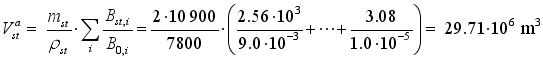
(1) Pollutant | Struct. steel Bst,i | Aluminum Bal,i | Composite Bcp,i2) | Concrete Bcr,i | Timber Btm,i | Threshold B0,i |
|---|---|---|---|---|---|---|
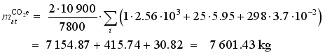
CO2 | 2.56 ·103 | 2.10 ·104 | 1.03 ·103 | 4.95 ·102 | 1.78 ·102 | 9.0 ·10-3 |
CO | 9.58 ·101 | 5.15 ·101 | 1.32 | 3.48 | 1.18 | 4.0 ·10-5 |
CH4 | 5.95 | 5.39 ·101 | 1.21 | 9.89 ·10-1 | 2.07 | 6.7 ·10-3 |
N2O | 3.70 ·10-2 | 2.94 ·10-1 | 4.80 ·10-3 | 1.51 ·10-2 | 1.25 10-3 | 1.0 ·10-7 |
PM Fe/Al3) | 4.40 ·10-1 | 1.65 | 1.05 ·10-1 | 7.50 ·10-2 | - | 1.0 ·10-7 |
PM Si/Ca/org3) | 4.20 ·10-2 | 2.70 ·10-1 | 5.05 ·10-1 | 5.88 ·10-1 | 1.35 10-1 | 3.0 ·10-7 |
SO2 | 3.28 | 1.27 ·101 | 2.51 ·10-3 | 2.80 ·10-1 | 1.10 10-1 | 1.2 ·10-6 |
NOx | 3.08 | 2.45 ·101 | 2.83 | 1.27 | 1.00 ·10-1 | 1.0 ·10-5 |
Styrene | - | - | 1.20 ·10-1 | - | - | 8.0 ·10-7 |
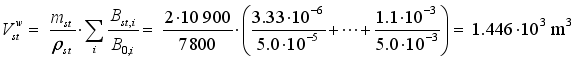
Pollutant | Struct. steel Bst,i | Aluminum Bal,i | Composite Bcp,i2) | Concrete Bcr,i | Timber Btm,i | Threshold B0,i |
|---|---|---|---|---|---|---|
Aluminum | 3.33·10-6 | 3.09 ·10-5 | 2.00 ·10-6 | 2.06 ·10-7 | - | 5.0 ·10-5 |
Ammonia | 4.58·10-3 | 4.23 ·10-2 | 1.10 ·10-3 | 2.38 ·10-4 | 9.16 ·10-4 | 2.2 ·10-3 |
Cadmium | 4.57 ·10-5 | 4.28 ·10-4 | 2.10 ·10-6 | 2.73 ·10-6 | 1.30 ·10-6 | 3.5 ·10-6 |
Copper | 1.96 ·10-8 | 1.82 ·10-7 | 7.90 ·10-4 | 0.99 ·10-9 | 6.50 ·10-5 | 2.0 ·10-4 |
Cyanide | 3.08 ·10-4 | 2.85 ·10-3 | 7.40 ·10-5 | 1.60 ·10-5 | - | 1.0 ·10-4 |
Fluoride | 1.03 ·10-1 | 6.49 ·10-3 | 2.00 ·10-4 | 3.51 ·10-3 | 5.20 ·10-6 | 1.5 ·10-3 |
Manganese | 6.07 ·10-6 | 5.64 ·10-5 | 3.60 ·10-6 | 3.79 ·10-7 | 1.04 ·10-6 | 5.0 ·10-5 |
Mercury | 1.57 ·10-4 | 1.45 ·10-3 | 7.00 ·10-7 | 7.53 ·10-6 | 6.00 ·10-9 | 5.0 ·10-6 |
Zinc | 1.98 | 5.44 ·10-2 | 1.40 ·10-3 | 1.69 ·10-1 | 6.00 ·10-4 | 5.0 ·10-3 |
Cobalt | 1.10 ·10-3 | 2.00 ·10-4 | 1.50 ·10-2 | 2.50 ·10-4 | 1.30 ·10-7 | 4.0 ·10-4 |
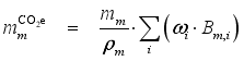
Greenhouse gas, GHG | Global warming potential, ω | |
|---|---|---|
CO2 | Carbon dioxide | 1 |
CH4 | Methane | 25 |
N2O | Nitrous oxide | 298 |
 (2)
(2) 
CVB | Commission of Navigation Managers, Netherlands |
FGPR | Fiberglass Reinforced Polymer |
FSC | Forest Stewardship Council |
GHG | Greenhouse Gas |
GWP | Global Warming Potential ω |
LCA | Life Cycle Analysis (or Assessment) |
LEED | Leadership in Energy and Environmental Design |
MJ | Mega-Joule (energy unit, 1 MJ ≈ 0.278 kWh) |
DMOW | Department of Mobility and Public Works, Belgium |
PEFC | Program for Endorsement of Forest Certification |
VNF | Voies Navigable de France |
WEF | World Economic Forum |
| [1] | Thwink.org. Finding and resolving the root causes of the sustainability problem, Sustainability, Clarkston, US, GA, 2014, |
| [2] |
WCED. Our Common Future (also called Brundtland Report), The United Nations World Commission on Environment and Development, Oxford University Press, Oxford UK, 1987,
https://sustainabledevelopment.un.org/content/documents/5987our-common-future.pdf |
| [3] | Daniel, R. A., Paulus, T. M. Lock Gates and Other Closures in Hydraulic Projects, Elsevier Butterworth-Heinemann, Oxford UK – Cambridge US, MA, 2019, pp. 768-858. |
| [4] | Daniel, R. A. Material selection for a navigation lock gate in view of ecological aspects (in Polish), Inżynieria Morska i Geotechnika, Gdańsk, 4(2022), pp. 187-199. |
| [5] |
Brolsma, J. U., Roelse, K. Waterway Guidelines (in Dutch), RWS, Verkeer en Scheepvaart, Rotterdam, 2011, pp. 1-177.
htps://repository.tudelft.nl/record/uuid:966c55b0-1d49-4a59-b46b-b9ce5b4ee936 |
| [6] | Mahadvi, A., Ries, R. Towards computational eco-analysis of building designs. Computers & Structures, New York, US, 67(1998), pp. 375-387, |
| [7] | Elferink, H. Exergie-analyse ook nuttig voor verbetering van producten (in Dutch). Energie- en Milieuspectrum, 11(1998), The Hague, pp. 22-25. |
| [8] | Daniel, R. A. Environmental considerations to structural material selection for a bridge, COBRAE European Bridge Engineering Conference, Rotterdam, March 2003, paper 17. |
| [9] | Daniel, R. A. Composite Traffic Ducts Can Help Improving Air Quality in Cities, Journal of Frontiers in Construction Engineering, June 2014, v3, i2, Hong Kong, pp. 20-29. |
| [10] | Szargut, J. Egzergia – Poradnik obliczania i stosowania (in Polish), Wydawnictwo Polotechniki Śląskiej, Gliwice, 2007, pp. 1-129, |
| [11] | Szargut, J. Exergy Method - Technical and Ecological Applications, WIT Press, Southampton UK – Billerica US, MA, 2005, pp. 1-192. |
| [12] | Wall, G. Exergetics, textbook on exergy available for download, Exergy Ecology Democracy, Bucaramanga, January 2009, pp. 1-151. |
| [13] | Verbeke, S. Energie als Indicator voor de duurzaamheid van gebouwen (in Dutch), master’s theisis, Ghent University, 2006, pp. 1-145. |
| [14] | Daniel, R. A. A Composite Bridge is Favoured by Quantifying Ecological Impact, Structural Engineering International, Zürich, 4(2010), pp. 385-391, |
| [15] | Sittig, M. World-wide Limits for Toxic and Hazardous Chemicals in Air, Water and Soil, Noyes Publications, Park Ridge, New Jersey, 1994. |
| [16] |
UNFCCC. Kyoto Protocol to the United Nations Framework Convention on Climate Change, Annex A, Kyoto, 1997, pp. 22-23.
https://unfccc.int/sites/default/files/resource/docs/cop3/l07a01.pdf#page=24 |
| [17] | SKAO. CO2 Performance Ladder, Foundation of Climate Friendly Procurement and Business (SKAO), Utrecht, 2025, |
| [18] | USGBC. LEED v4 for Building Operation and Maintenance, U.S. Green Building Council, Washington DC, January, 2018, update 2025 in |
| [19] | WEF. Industry Agenda. Environmental Sustainability Principles for the Real Estate Industry, WEF, Geneva, 2016, p. 10. |
| [20] | Daniel, R. A., Hermans, I. Belgian sea locks – proven solution for a safe navigation access to harbors, Inżynieria Morska i Geotechnika, Gdańsk, 4(2020), pp. 188-203. |
| [21] | Hermans, I., Cock W. de. Renovation of Van Cauwelaert Lock (Port of Antwerp, Belgiun) – Special design considerations for the new rolling gates, proceedings of the PIANC AGA Seminar, Beijing, 2008, pp. 496-502. |
| [22] | Daniel, R. A., Brekoo, A., Mulder, A. J. New materials for an old lock - Innovation with a tribute to old expertise (in Dutch), Land + Water, 11(2001), pp. 36-38. |
| [23] | Flemish Government. Standaardbestek 260 voor kunstwerken en waterbouw v. 2.0, Errata en aanvullingen (in Dutch), MOW, Dec. 2018, Brussels, PDF pp. 1-366. |
| [24] | Flemish Government. Standaardbestek 260 voor kunstwerken en waterbouw v. 2.0a: Hout en houten constructiedelen (in Dutch), MOW, Brussels, 2021, PDF pp. 20-25. |
| [25] | Bomen Over: Azobé – Lophira alata (in Dutch), Het Houtblad, February 2005, Centrum Hout, Almere, pp. 28-34. |
| [26] | Kuilen, J. W. G. van de, Blass, H. J. Mechanical properties of azobé (Lophira alata), Holz als Roh- und Werkstoff, 63(2005), pp. 1-10, |
APA Style
Daniel, R. A., Hermans, I. (2025). Towards Unbiased Environmental Material Selection for a Structure - Case Study of a Navigation Lock Gate. Journal of Civil, Construction and Environmental Engineering, 10(5), 191-206. https://doi.org/10.11648/j.jccee.20251005.13
ACS Style
Daniel, R. A.; Hermans, I. Towards Unbiased Environmental Material Selection for a Structure - Case Study of a Navigation Lock Gate. J. Civ. Constr. Environ. Eng. 2025, 10(5), 191-206. doi: 10.11648/j.jccee.20251005.13
@article{10.11648/j.jccee.20251005.13,
  author = {Ryszard A. Daniel and Ivar Hermans},
  title = {Towards Unbiased Environmental Material Selection for a Structure - Case Study of a Navigation Lock Gate
},
  journal = {Journal of Civil, Construction and Environmental Engineering},
  volume = {10},
  number = {5},
  pages = {191-206},
  doi = {10.11648/j.jccee.20251005.13},
  url = {https://doi.org/10.11648/j.jccee.20251005.13},
  eprint = {https://article.sciencepublishinggroup.com/pdf/10.11648.j.jccee.20251005.13},
  abstract = {This paper presents a few relatively simple and transparent methods of material selection for a civil engineering structure in view of sustainability. It is addressed to practicing engineers, designers, production managers, other professionals and students intending to take account of sustainability when choosing the material for new structures or maintaining the existing structures. The presented methods are illustrated by a case study for a navigation lock gate. The materials that are currently applicable for this structure are: structural steel, stainless steel, aluminum, polymer composite, reinforced concrete and timber. Three most common sustainability criteria have been considered, which are: 1. Energy use, 2. Loads (pollutions) to the environment, 3. CO2 emissions (called also “carbon footprint”). In the current engineering practice, sustainability criteria and the related material choices are often prone to emotional reactions and driven by politicized or biased arguments. This paper aims to help engineers deal with this issue by focusing on verifiable aspects of sustainable construction. An attempt has been made to encourage critical approach and corrections in available databases for a better mach with the analyzed projects. The analysis covers the so-called “cradle to grave” life cycle, with some focus on manufacturing – the process that usually gives the highest environmental impact. The impact of less essential or less determined processes has been approximated, based on the authors’ experience in design and management of hydraulic structures. In order to quantify the required materials, conceptual designs of the lock gate have been developed in all materials. The structure type and sizes represent the medium-range of lock gate applications, which allows for general conclusions. Such conclusions must, however, take specific technological and other feasibility restraints into account.
},
 year = {2025}
}
TY  - JOUR
T1  - Towards Unbiased Environmental Material Selection for a Structure - Case Study of a Navigation Lock Gate

AU  - Ryszard A. Daniel
AU  - Ivar Hermans
Y1  - 2025/10/27
PY  - 2025
N1  - https://doi.org/10.11648/j.jccee.20251005.13
DO  - 10.11648/j.jccee.20251005.13
T2  - Journal of Civil, Construction and Environmental Engineering
JF  - Journal of Civil, Construction and Environmental Engineering
JO  - Journal of Civil, Construction and Environmental Engineering
SP  - 191
EP  - 206
PB  - Science Publishing Group
SN  - 2637-3890
UR  - https://doi.org/10.11648/j.jccee.20251005.13
AB  - This paper presents a few relatively simple and transparent methods of material selection for a civil engineering structure in view of sustainability. It is addressed to practicing engineers, designers, production managers, other professionals and students intending to take account of sustainability when choosing the material for new structures or maintaining the existing structures. The presented methods are illustrated by a case study for a navigation lock gate. The materials that are currently applicable for this structure are: structural steel, stainless steel, aluminum, polymer composite, reinforced concrete and timber. Three most common sustainability criteria have been considered, which are: 1. Energy use, 2. Loads (pollutions) to the environment, 3. CO2 emissions (called also “carbon footprint”). In the current engineering practice, sustainability criteria and the related material choices are often prone to emotional reactions and driven by politicized or biased arguments. This paper aims to help engineers deal with this issue by focusing on verifiable aspects of sustainable construction. An attempt has been made to encourage critical approach and corrections in available databases for a better mach with the analyzed projects. The analysis covers the so-called “cradle to grave” life cycle, with some focus on manufacturing – the process that usually gives the highest environmental impact. The impact of less essential or less determined processes has been approximated, based on the authors’ experience in design and management of hydraulic structures. In order to quantify the required materials, conceptual designs of the lock gate have been developed in all materials. The structure type and sizes represent the medium-range of lock gate applications, which allows for general conclusions. Such conclusions must, however, take specific technological and other feasibility restraints into account.

VL  - 10
IS  - 5
ER  -
Independent Researcher, Gouda, The Netherlands
Department of Mobility and Public Works (DMOW), Brussels, Belgium
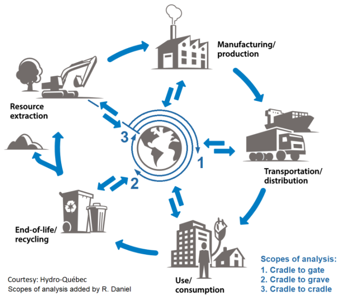
Figure 1. Main phases of Life Cycle Analysis (LCA), based on image by Hydro-Québec.
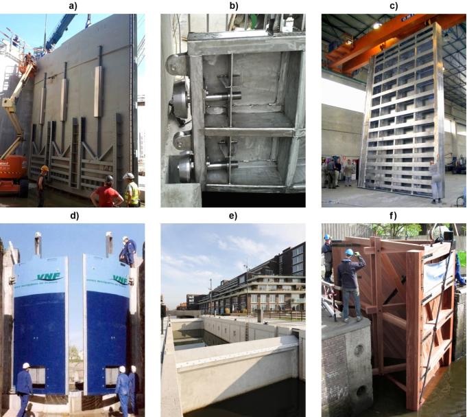
Figure 2. Examples of lock gates in 6 considered material options as described in Section 2 above.
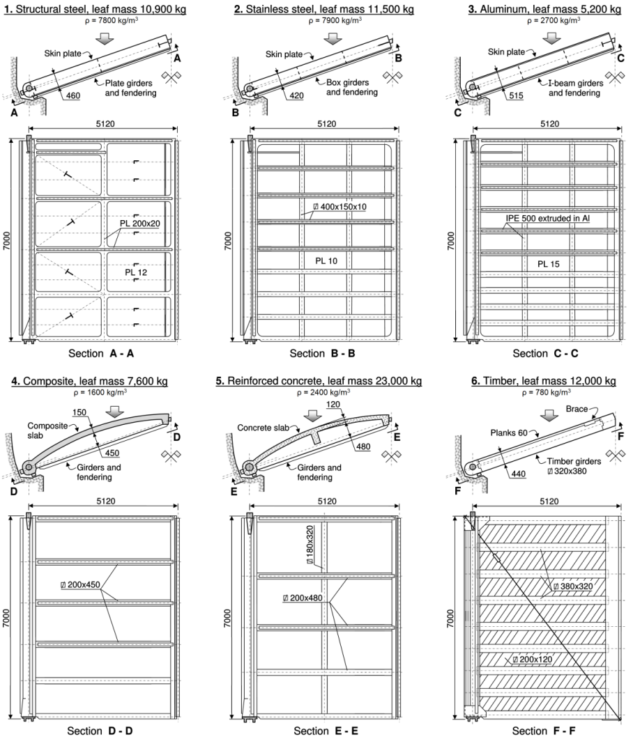
Figure 3. Conceptual designs of a lock gate in 6 considered material options.
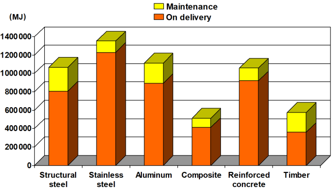
Figure 4. Energy consumption for a lock gate in 6 material options.
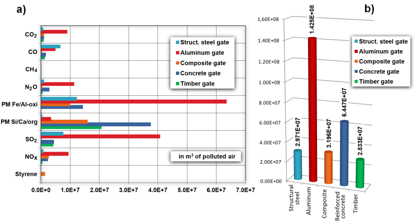
Figure 5. Emissions to air for a lock gate in 5 optional materials: a) per pollutant; b) in total critical volumes of polluted air.
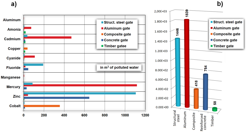
Figure 6. Emissions to water for a lock gate in 5 optional materials: a) per pollutant; b) in total critical volumes of polluted water.
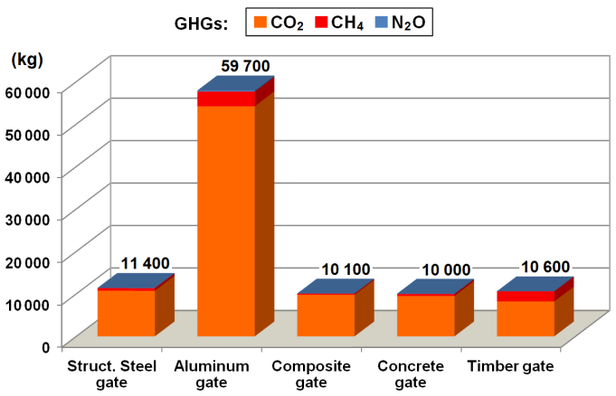
Figure 7. CO2e emissions for a lock gate in 5 material options.
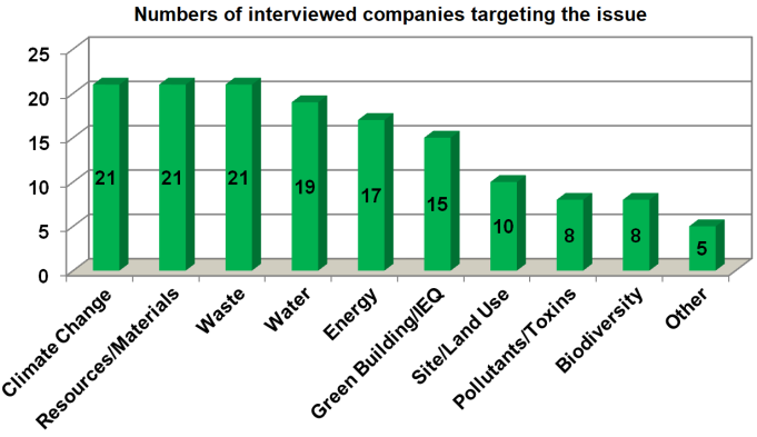
Figure 8. Environmental issues targeted in company principles.
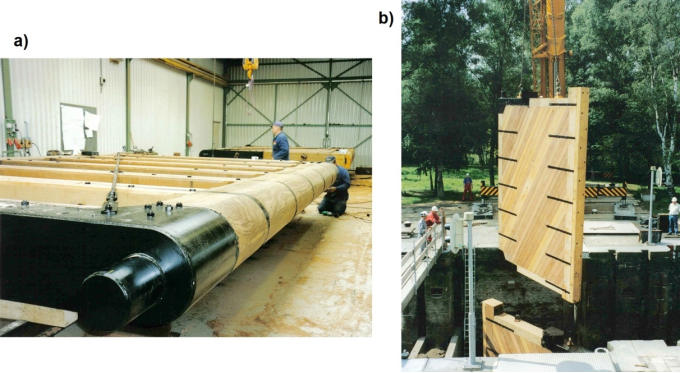
Figure 9. Lock gate in Wilhelmina Canal, Tilburg, Netherlands, photos R. Daniel: a) in fabrication; b) installation on the site.
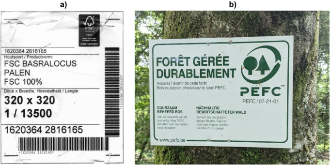
Figure 10. Certificates of sustainable forest management, photos R. Daniel: a) from gate depicted in Figure 2f, The Netherlands; b) in the forests of Ardennes, Belgium.
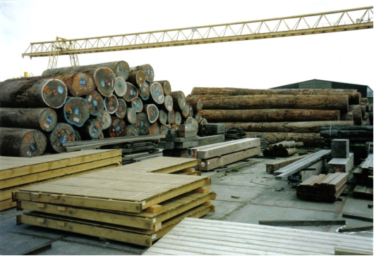
Figure 11. Tropical timber at storage yards of Wijma BV in Kampen, The Netherlands, photo R. Daniel.
Information