1. Introduction
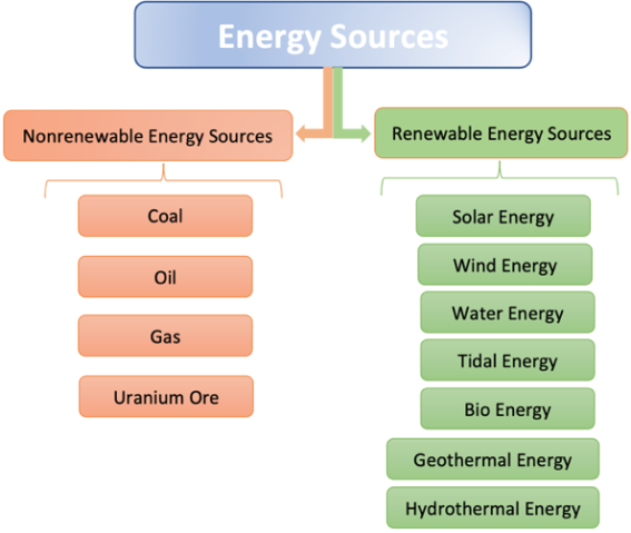
One of the main challenges in vacuum microwave electronics is developing new sources of electromagnetic radiation, together with enhancing the parameters and performance of existing tubes that generate microwave radiation. The fact that electromagnetic radiation can propagate through all media and penetrate inside a volume of materials is its undeniable advantage, and this fact sets it apart, for example, from thermal radiation. The quantitative measure of electromagnetic radiation is based on the energy of the electromagnetic field. To understand the growing importance and value of electromagnetic energy in modern technology, it is essential to assess its role within the broader spectrum of available energy types. Here, it is important to recognize that each type of energy has its own specific energy sources. Existing natural energy sources can be divided into two main classes. These are natural energy sources (or non-renewable energy sources: coal, oil, gas, and uranium ore) and alternative energy sources (or renewable energy sources), created by humans thanks to modern scientific achievements and various natural phenomena, including sunlight, wind, waves, tides, medium temperature differences, and waste of plant and animal origin. The widespread development and introduction of alternative energy sources have laid the groundwork for a new direction in the energy sector, known as clean or green energy. The modern classification of existing energy sources is shown in
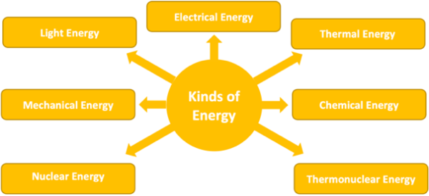
Figure 1. These sources enable the production of different types of energy. Classifying energy types from a physical perspective allows us to identify the main types, as shown in
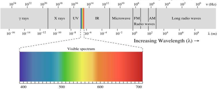
Figure 2. It should be noted that several of the presented types of energy (for example, sunlight or heat) are forms of electromagnetic radiation that contain electromagnetic energy and propagate as electromagnetic waves of different frequencies (
f) or wavelengths (
λ = c / f, where
c is the speed of light). Depending on their frequency (or wavelength), electromagnetic waves form the full spectrum of electromagnetic radiation, as shown in
Figure 3. As shown, electromagnetic radiation is a continuous spectrum of wavelengths (or frequencies), categorized into specific ranges—from long-wave radio waves to gamma rays. It is essential to recognize the practical applications of electromagnetic waves in addressing the challenges of radar, remote sensing, wireless communications, and long-distance energy transmission.
The first person to mention energy transfer over a wireless network was Nikola Tesla
| [1] | N. Tesla, The Transmission of Electric Energy Without Wires (The Thirteenth Anniversary Number of the Electrical World and Engineer). New York: McGraw-Hill, Mar. 5, 1904. |
[1]
. W. C. Brown pioneered the history of wireless energy transmission through his research on wireless communication technology and remote sensing
| [2] | W. C. Brown, “The history of power transmission by radio waves,” IEEE Trans. Microwave Theory Tech., vol. MTT-32, pp. 1230–1242, 1984. |
[2]
. A frequency of 2,45 GHz was used for energy transmission, with continuous magnetrons and klystrons recognized as sources of powerful electromagnetic radiation. Subsequent studies have demonstrated that magnetrons are better suited for wireless energy transmission systems and space-based solar power plants due to their high output power, efficiency, low weight, cost-effectiveness, and favorable power-to-weight ratio. An oven magnetron operating at a frequency of 2,45 GHz and an output power of 800 Watts at a voltage of 4.1 kV was chosen as the source of electromagnetic radiation. Long-term use of the magnetron in industrial and domestic microwave heating has demonstrated its high reliability and durability. Research conducted over the years has led to improvements in its parameters, explicitly enhancing the spectral characteristics
| [3] | K. Yamamoto, H. Kurronuma, T. Koinuma, N. Tashiro, Experimental Study of Noise Generated by Magnetrons for Microwave Ovens. J. of Microwave Power. 1981, vol. 16, # 3 & 4, pp. 271-276. |
| [4] | H. Saito, M. Kume, T. Kawaguchi, Improvements of Performance of Magnetron for Microwave Oven. Toshiba Review. 1985, vol. 40, # 6, pp. 531-534. |
| [5] | G. I. Churyumov, T. I. Frolova, A. V. Gritsunov, O. M. Nikitenko, V. N. Zin'kovsky, The magnetrons - EMI sources: computer modeling and experimental investigations. Proceedings International Symposium on Electromagnetic Compatibility (EMC Europe 2004). - Vol. 1. - Eindhoven (The Netherlands). - 2004, September 6-10. - pp. 327-331. |
| [6] | Hideyuki Obata, Naoki Tsuji, and Kuniyoshi Furumoto, Frequency Bandwidth Narrowing Technology for Pulsed Magnetrons. IEEE Transactions on Electron Devices, vol. 56, # 12. December 2009. pp. 3191-3195. https://doi.org/10.1109/TED.2009.2031004 |
| [7] | M. Imran Tahir, Frequency and Phase Locking of a CW Magnetron (with a digital phase locked loop using pushing characteristics). Engineering Department, Lancaster University, Lancaster, England, September 2008. pp. 1-144. ( https://eprints.lancs.ac.uk/id/eprint/76594 ). |
[3-7]
, increasing the output power of a single magnetron to 3 kW or more, and employing the principle of summing output power from multiple magnetrons
| [8] | X. Chen, B. Yang, N. Shinohara, and C. Liu, "Low-Noise Dual-Way Magnetron Power-Combining System Using an Asymmetric H-Plane Tee and Closed-Loop Phase Compensation," in IEEE Transactions on Microwave Theory and Techniques, vol. 69, no. 4, pp. 2267-2278, April 2021, https://doi.org/10.1109/TMTT.2021.3056550 |
[8]
, as well as ensuring compliance with electromagnetic compatibility requirements (for instance, by developing a similar magnetron that operates at a frequency of 2.48 GHz
).
Figure 1. Energy sources.
Figure 2. Existing kinds of energy.
Meanwhile, there is a more straightforward way to address several of the issues mentioned above, such as modifying the design of the conventional magnetron. One way to solve such a problem is to apply an additional device for the existing design of the conventional magnetron, for example, a second RF energy output
| [11] | Patent of Ukraine No 42293, Magnetron generator. G. I. Churyumov, T. I. Frolova, A. I. Ekezly, K. V. Sivokon, 200901408, 19.02.2009 (in Ukrainian). |
[11]
. As illustrated in the previous study, incorporating a second (passive) RF output in the conventional magnetron design enhances its functional capabilities
| [12] | Shuang Qiu, Nan-nan Wang, Gennadiy I. Churyumov, A Magnetron Using an Additional External Reactive Load for Frequency Tuning: Theory Features and Experiment. IEEE Transactions on Electron Devices, Vol. 71, # 3, March 2024. pp. 2147-2152, https://doi.org/10.1109/TED.2024.3359586 |
| [13] | Gennadiy I. Churyumov, Nan-nan Wang, Volodymyr P. Gerasimov, Wei Li, Low-Voltage Kᵤ-Range Magnetron with Two Outputs of Energy: Design Features and Main Advantages. IEEE Transactions on Electron Devices. Vol. 67, # 12, December 2020. pp. 5743-5749, https://doi.org/10.1109/TED.2020.3029129 |
[12, 13]
. Experimental confirmation has been obtained for the low-voltage X- and Ku-band double-output magnetrons. It has been demonstrated that such a magnetron design enables the stabilization of the magnetron frequency (up to 10
-7 | [12] | Shuang Qiu, Nan-nan Wang, Gennadiy I. Churyumov, A Magnetron Using an Additional External Reactive Load for Frequency Tuning: Theory Features and Experiment. IEEE Transactions on Electron Devices, Vol. 71, # 3, March 2024. pp. 2147-2152, https://doi.org/10.1109/TED.2024.3359586 |
[12]
), achieving maximum frequency tuning within the ranges of 300 and 250 MHz, respectively, and implementing synchronization and frequency modulation modes
| [14] | Gennadiy Churyumov, Shuang Qiu, Nan-nan Wang, The Low-Voltage X, Ku and W-Bands Magnetrons with Two Energy Outputs: New Possibilities. 24th International Vacuum Electronics Conference (IVEC 2023), (25-29 April 2023, Chengdu, China). 2023. |
| [15] | G. Churyumov, Chen Lijia, Ihor Kuzmychov, A Magnetron with Two RF Energy Outputs for Advanced Radar Systems. International Radar Conference 2024, 21 – 25 October 2024, Rennes, France. |
| [16] | G. Churyumov, Chen Lijia, Ihor Kuzmychov, Using a Varactor for Frequency Tuning a Ku-Band Low-Voltage Magnetron Double-Output Magnetron. V International Conference on Electrical, Computer and Energy Technologies (ICECET 2025), (3-6 July 2025, Paris, France). – 2025. |
[14-16]
.
Figure 3. Spectrum of electromagnetic radiation.
This paper examines new magnetron designs that include a second (passive) RF output, distinguishing them from traditional designs. It details the operation of low-voltage double-output magnetrons across a broad frequency spectrum, from X and Ku bands to W band. The design approach for these magnetrons is used to develop power double-output magnetrons, such as oven double-output magnetrons. It discusses changes in parameters such as frequency and output power, with an example involving an installation that utilizes a microwave-driven sulfur lamp, which emits intense electromagnetic radiation in the optical range. The benefits of this innovative magnetron design for wireless power transmission via electromagnetic radiation are highlighted.
2. The Double-Output Magnetrons
One method to improve the performance of conventional magnetrons is by adding a second RF output to regulate their operation
| [11] | Patent of Ukraine No 42293, Magnetron generator. G. I. Churyumov, T. I. Frolova, A. I. Ekezly, K. V. Sivokon, 200901408, 19.02.2009 (in Ukrainian). |
| [12] | Shuang Qiu, Nan-nan Wang, Gennadiy I. Churyumov, A Magnetron Using an Additional External Reactive Load for Frequency Tuning: Theory Features and Experiment. IEEE Transactions on Electron Devices, Vol. 71, # 3, March 2024. pp. 2147-2152, https://doi.org/10.1109/TED.2024.3359586 |
| [13] | Gennadiy I. Churyumov, Nan-nan Wang, Volodymyr P. Gerasimov, Wei Li, Low-Voltage Kᵤ-Range Magnetron with Two Outputs of Energy: Design Features and Main Advantages. IEEE Transactions on Electron Devices. Vol. 67, # 12, December 2020. pp. 5743-5749, https://doi.org/10.1109/TED.2020.3029129 |
[11-13]
.
2.1. The Low-Voltage Double-Output X and Ku Band Magnetrons
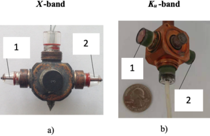
Figure 4 shows the experimental prototypes of the developed low-voltage double-output magnetrons for
X and
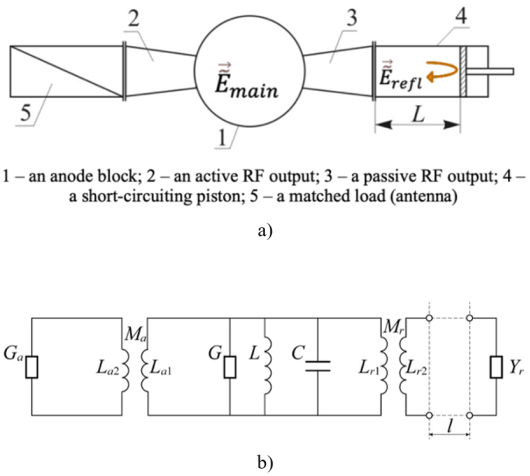
Ku bands. A general scheme for the RF turn-on of the double-output magnetron (a) and its equivalent circuit (b) is illustrated in
Figure 5. As can be seen, the active RF output 2 is matched with the external load 5, while the passive (or reactive) RF output 3 connects to a purely reactive load (for example, a short-circuiting piston 4). In this case, the input impedance of the passive output is reactive and can be expressed as
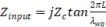
,
(1) where - characteristic resistance of a waveguide; L - length of a short-circuited waveguide section; - wavelength in a transmission line.
The circuit consists of an equivalent parallel
circuit (a resonant anode block) characterized by parameters
L,
C, and
G, and two ideal transformers coupled with the equivalent
circuit, and two loads: the purely reactive load
and the matched active load
. The coupling magnitude of the equivalent
circuit with the active and passive RF outputs is determined by the transformation ratios
and
, respectively. As indicated in
| [12] | Shuang Qiu, Nan-nan Wang, Gennadiy I. Churyumov, A Magnetron Using an Additional External Reactive Load for Frequency Tuning: Theory Features and Experiment. IEEE Transactions on Electron Devices, Vol. 71, # 3, March 2024. pp. 2147-2152, https://doi.org/10.1109/TED.2024.3359586 |
| [13] | Gennadiy I. Churyumov, Nan-nan Wang, Volodymyr P. Gerasimov, Wei Li, Low-Voltage Kᵤ-Range Magnetron with Two Outputs of Energy: Design Features and Main Advantages. IEEE Transactions on Electron Devices. Vol. 67, # 12, December 2020. pp. 5743-5749, https://doi.org/10.1109/TED.2020.3029129 |
[12, 13]
, the necessary and sufficient conditions for frequency tuning and steady-state magnetron operation are expressed by the following expressions
and
(3)
where - the coupling factor of the active RF output; - the coupling factor for the passive (reactive) RF output; - the loaded Q-factor of the resonant anode block; - own (unloaded) Q-factor; and - the external Q-factors for the active and passive RF outputs, respectively.
Figure 4. Experimental prototypes of the low-voltage double-output magnetrons.
The main parameters of a low-voltage double-output X-band magnetron are as follows: the frequency (at the midpoint of the band) is 9420 MHz; the heating voltage is 6.3 V; the anode voltage is 580 V; the magnetic field is 0.21 T; the anode current is 0.085 A; and the output power is 18.6 W. Additionally, a heater-type cathode and air cooling of the anode block are used.
The similar parameters for a low-voltage double-output Ku-band magnetron are as follows: the frequency (at the midpoint of the band) is 13300 MHz; the heating voltage is 6.3 V; the anode voltage is 480 V; the magnetic field is 0.21 T; the anode current is 0.075 A; and the output power is 15.4 W. Additionally, a heater-type cathode and air cooling of the anode block are used.
Thus, applying such a design to a magnetron allows for greater functionality, including frequency tuning, stabilization, and modulation.
2.1.1. Frequency Tuning (Adjustment)
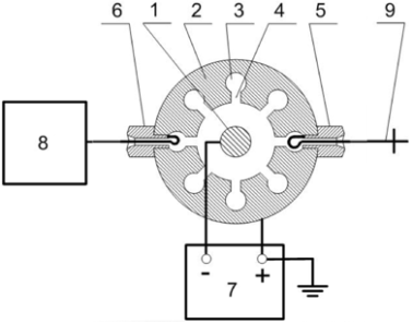
Figure 6. General diagram of the magnetron connection in the frequency tuning mode.
1 – cathode, 2 – anode block, 3 and 4 – resonant structure “slot–hole”, 5 – passive (or reactive) RF output, 6 – active RF output, 7 – power supply, 8 – matched load, 9 - short-circuiting piston
The general diagram of how a double-output magnetron operates during frequency tuning (or adjustment) is shown in
Figure 6 | [11] | Patent of Ukraine No 42293, Magnetron generator. G. I. Churyumov, T. I. Frolova, A. I. Ekezly, K. V. Sivokon, 200901408, 19.02.2009 (in Ukrainian). |
[11]
. As observed, moving the short-circuiting piston 9 changes the reactive load according to (1), which in turn shifts the resonance frequency of the anode block or the frequency tuning (adjustment).
2.1.2. Frequency Stabilization
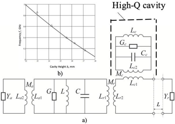
The frequency stability of conventional magnetrons is usually not less than ~ 10-5, which is insufficient for use in modern radar systems. Several factors can cause this frequency instability, such as fluctuations and instability of operating voltages—including anode and filament voltages—and the presence of external electrical circuits that control the magnetron's operating regime, including filament and microwave circuits. Thermal effects also play a role: they can alter the internal geometrical dimensions of the anode block, especially in the short millimeter-wave bands, and they influence emission processes on the cathode surface, leading to uncontrolled additional electron emission. Solving the problem of improving the stability of a conventional magnetron involves a multi-parametric and complex approach. A more straightforward solution involves using a high-Q cavity to stabilize the magnetron frequency. In the case of a double-output magnetron, this cavity can be integrated into the microwave circuit of the passive RF output via an H-plane tee.
The equivalent circuit of the double-output magnetron, which employs a high-Q cavity for frequency stabilization, along with the frequency tuning curve of this cavity, is shown in
Figure 6 | [15] | G. Churyumov, Chen Lijia, Ihor Kuzmychov, A Magnetron with Two RF Energy Outputs for Advanced Radar Systems. International Radar Conference 2024, 21 – 25 October 2024, Rennes, France. |
[15]
. For the frequency stabilization studies, a prototype of an X-band low-voltage double-output magnetron was used. The high-Q cavity was a tunable circular resonator with a radius of 25 mm, excited in the TE
011 mode. Its unloaded Q-factor is approximately 1780. Both the theoretical and experimental frequency tuning curves are presented in
Figure 7b. The frequency tuning curve of the stabilizing cavity was obtained using the CST code.
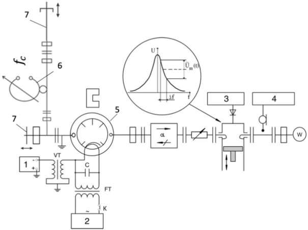
A general scheme for measuring the frequency stability of the double-output magnetron is shown in
Figure 8. This method employs a direct detection approach, utilizing a frequency discriminator based on a transmission resonator to measure the frequency fluctuations of the active magnetron. The main principle involves converting frequency fluctuations into voltage variations of the measured signal (see
Figure 8). The resonator in the circuit is tuned so that its steepest, most linear response region aligns with the spectral width of the signal being analyzed. After detection, the signal is fed into an oscilloscope 3 (see
Figure 8).
Figure 8. A general scheme for the measurement of the frequency deviation and its stabilization.
1 – a high-voltage power supply; 2 – a filament voltage power supply; 3 – an oscilloscope; 4 – a spectrum analyzer; 5 – a double-output magnetron; 6 – a high-Q stabilizing resonator; 7 – short-circuiting pistons
2.1.3. Frequency Modulation
Figure 9. Functional turn-on circuit of the double-output magnetron in modulation mode.
1 – an anode block; 2 and 3 - active and passive RF outputs; 4 – a reactive load; 5 – a matched load; 6 - matching transformers; 7 – a varactor diode; 8 – a short-circuit piston.
As shown in
| [16] | G. Churyumov, Chen Lijia, Ihor Kuzmychov, Using a Varactor for Frequency Tuning a Ku-Band Low-Voltage Magnetron Double-Output Magnetron. V International Conference on Electrical, Computer and Energy Technologies (ICECET 2025), (3-6 July 2025, Paris, France). – 2025. |
[16]
, applying a variable reactive load to the passive RF output alters the generated frequency and facilitates frequency tuning. A semiconductor diode with electrically controlled capacitance (varactor) should be used for reactivity to improve speed, ensure smoother frequency tuning, and make controlling the frequency change easier.
Figure 9 shows a functional circuit of a double-output magnetron, where a diode section containing a varactor is connected to the magnetron's reactive RF output.
The device is a tunable control waveguide line modified with a varactor and operated by a short-circuit piston. The frequency tuning characteristic, which changes with the bias voltage applied to the diode, depends on the device's total equivalent length and the position of the varactor. To maximize the frequency tuning range while reducing losses, it is crucial to select the optimal placement of the diode within the waveguide. The diode should be positioned at the point of maximum microwave electric field intensity, specifically away from the short-circuit piston, to enhance the varactor's coupling to the transmission line.
In the continuous operation of the magnetron, using a varactor in the diode section limits the potential power output to tens of watts. Employing the latest diode designs and advancements for high-power magnetron operation (in the hundreds of watts during continuous run) is essential, as the diode must dissipate significant power.
Applying modulators as a load for the second (reactive) energy output in low-voltage CW magnetrons with two energy outputs enables the creation of various communication systems, including broadband ones.
2.2. A Double-Output W Band Magnetron
It is known that the interaction mechanism in magnetrons is based on the interaction between the closed electron beam and the oscillations of the π-mode, which are excited within the electrodynamic structure of the magnetron's anode block. At the same time, using the π-mode oscillations in magnetrons operating in the short-wave part of the millimeter-wave spectrum is highly questionable because it requires high anode voltages and strong magnetic fields. Additionally, it is necessary to consider that the geometrical size of the interaction space in a magnetron scales approximately with the wavelength of the generated oscillation. At the same time, the magnetic field strength varies inversely with the wavelength, i.e.
, where
is the anode radius,
is the magnetic field strength, and
is the wavelength. As a result, decreasing the wavelength also reduces the radii of the cathode and anode, which raises the risk of vacuum breakdown as the anode voltage increases. An alternative operating mode was employed for designing magnetrons in the millimeter-wave range, specifically operation in the π/2 mode
| [17] | Електроніка й радіофізика міліметрових і субміліметрових радіохвиль» під загальною ред. акад. АН УРСР А. Я. Усикова. - Наукова думка.: - Київ. - 366 с. (in Ukrainian). |
[17]
. Recent investigations using 3-D simulations have improved our understanding of electron-wave interactions in these magnetrons. As a result, experimental measurements have shown output parameters, including a frequency of 140 GHz, a peak output power ranging from 5 to 11 kW, and an efficiency from 1.5 to 4.5%, with the anode voltage varying from 8 to 15 kV. The magnetron also demonstrated high frequency stability (~10
-6) and the potential for mechanical frequency tuning (~0.3% of the central frequency) [see, for example, 18].
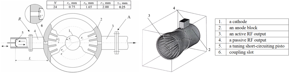
Applying the second RF energy output in the THz-magnetron presents a complex challenge due to its manufacturing features. The potential designs of a magnetron with two RF energy outputs are schematically shown in
Figure 10. In the first case, we used a conventional magnetron with two RF outputs: an active (A-3) and a passive (reactive) (R-4). The active RF output is matched with the external load, while the load of the passive RF output is purely reactive. For this, we used the tuning short-circuiting piston 5, which has a strictly reactive input resistance. Moving the piston 5 changes the reactive conductivity of the anode block, thus tuning (or adjusting) its resonant frequency. As shown in
| [12] | Shuang Qiu, Nan-nan Wang, Gennadiy I. Churyumov, A Magnetron Using an Additional External Reactive Load for Frequency Tuning: Theory Features and Experiment. IEEE Transactions on Electron Devices, Vol. 71, # 3, March 2024. pp. 2147-2152, https://doi.org/10.1109/TED.2024.3359586 |
| [13] | Gennadiy I. Churyumov, Nan-nan Wang, Volodymyr P. Gerasimov, Wei Li, Low-Voltage Kᵤ-Range Magnetron with Two Outputs of Energy: Design Features and Main Advantages. IEEE Transactions on Electron Devices. Vol. 67, # 12, December 2020. pp. 5743-5749, https://doi.org/10.1109/TED.2020.3029129 |
[12, 13]
, achieving the desired tuning frequency in a double-output magnetron requires the passive RF output coupling to be stronger than the active RF output coupling with the anode block. We used different designs of the coupling slots for the active and passive RF outputs to accomplish this. Additionally, as shown in
| [12] | Shuang Qiu, Nan-nan Wang, Gennadiy I. Churyumov, A Magnetron Using an Additional External Reactive Load for Frequency Tuning: Theory Features and Experiment. IEEE Transactions on Electron Devices, Vol. 71, # 3, March 2024. pp. 2147-2152, https://doi.org/10.1109/TED.2024.3359586 |
[12]
, the total electromagnetic energy stored in such a complex electrodynamic structure, which includes the anode block and two RF energy outputs coupled via the coupling elements, must satisfy the following expression (3).
The construction of the second type of double-output magnetron, as shown in
Figure 10b, features a key aspect involving the diffraction output of microwave radiation as an active RF output. We used a dielectric disk to separate the vacuum section of the interaction space of the anode block from its non-vacuum section. In this setup, electromagnetic energy from the magnetron's interaction space is radiated into free space. Regarding the electrodynamic structure of the anode block in the magnetrons, we employed the comb structure shown in
Figure 10a and 10b.
3. A Double-Output Oven Magnetron Design
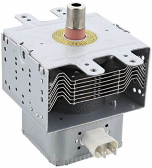
The general view of the oven magnetron is shown in
Figure 11.
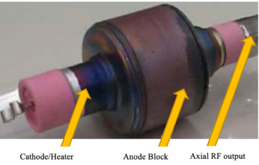
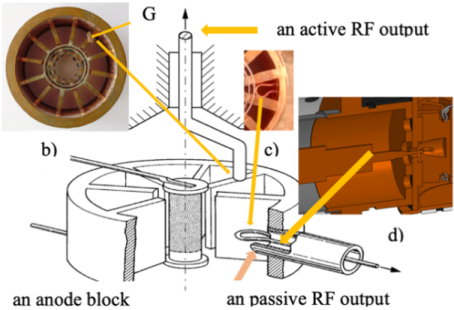
Figure 12 shows the experimental specimen of the conventional oven magnetron. This design features key components, including a cathode assembly, an anode block, and an axial (active) RF output. The overall layout of the new oven magnetron design is illustrated in
Figure 13. As shown, the second (passive) RF output is asymmetrically positioned relative to the main active RF output. Typically, the anode block of an oven magnetron features a 10- (or 12-) cavity double-ring-strapped resonant system that functions as a delay structure (see
Figure 13b). A loop and a coaxial transmission line are used to couple power from the magnetron (see
Figure 13c, d). The size and orientation of the coupling loop affect the coupling strength.
Figure 10. Schematic view of the designs of the magnetron with two RF outputs.
Figure 11. A general view of the conventional oven magnetron
Figure 12. An anode block specimen of the conventional oven magnetron without a magnet.
Figure 13. General scheme for a possible design of the double-output oven magnetron.
One advantage of the oven double-output magnetron is its ability to tune frequency and control output power. The quality of this magnetron is very important and interesting for solving problems related to microwave pumping.
Among the promising light sources available, particular attention is focused on developing plasma lighting devices that utilize an electrodeless sulfur lamp with microwave excitation
| [19] | Dolan I. T., Ury M. G., Wood C. H. A Novel High-Efficacy Microwave-Powered Light Source. Presented as a Landmark. – In: Sixth International Symposium on the Science and Technology of Light Sources, 1992, Technical University of Budapest. |
[19]
. In 2010, the AS 1300 lighting system was introduced, which consists of a power supply, a microwave generator (magnetron), and a light module. However, the complexity of the design and the high costs associated with this lighting technology limited its production to a few devices.
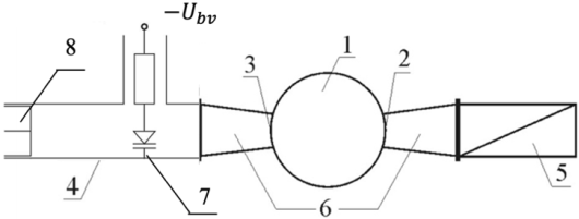
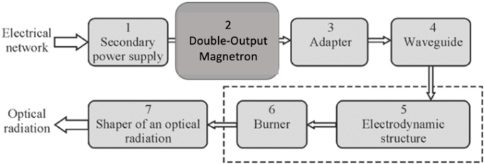
Figure 14 depicts a general scheme of a plant for generating optical radiation in the visible wavelength range (visible light) using a plasma illumination device that employs an electrodeless sulfur lamp with microwave excitation. It is essential to note that the plant converts electrical energy into the energy of light waves in stages. In the first stage, secondary power source 1 converts the alternating voltage of 220
V at a frequency of 50
Hz into a constant voltage of 3.8–4.2
kV, delivered to the magnetron's anode. In the second stage, magnetron generator 2 converts DC energy into electromagnetic oscillation energy. As a result, the oscillations at the magnetron's output in waveguide 4 have a frequency of 2.45 GHz and an output continuous power of ~ 800 W. These oscillations excite the electromagnetic field in electrodynamic structure 5, where the sulfur lamp is positioned at the maximum of the electric field. In the third stage, physicochemical processes take place inside the sulfur lamp under the influence of the electromagnetic field, producing optical radiation in the visible wavelength range (380–780 nm). This radiation is then focused and emitted into free space.
Figure 14. General scheme of energy conversion in the plasma lighting device.
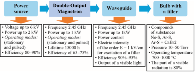
Figure 15 shows the main parts of the lighting device and its key parameter values. The magnetron is a crucial element in any lighting system that utilizes a sulfur lamp. Its primary role is to produce electromagnetic radiation at ~ 2.45 GHz and deliver a continuous output power of at least 800 W.
Figure 15. The list of basic elements and parameters of the lighting device.
When analyzing the radiation from a sulfur microwave lamp, researchers discovered that it emits light across the entire spectrum of wavelengths. Its spectrum appears as a continuous band that gradually shifts in color from red to purple (380-780 nm). Its maximum brightness is in the green wavelength region, and its efficiency is ~ 20%
| [20] | G. Churyumov, T. Frolova, “Microwave Energy and Light Energy Transformation: Methods, Schemes and Designs. Microwave Energy and Light Energy Transformation: Methods, Schemes and Designs” // In the book “Emerging Microwave Technologies in Industrial, Agricultural, Medical and Food Processing.” Edited by Kok Yeow You, IntechOpen, 2018. pp. 75-91. https://doi.org/10.5772/intechopen.73755 |
[20]
. Its radiation spectrum closely resembles the solar spectrum and the spectral characteristics of the human eye.
Optimizing the operational process of a lighting system that utilizes a sulfur lamp depends on the magnetron's ability to adjust its output power. As illustrated in
Figure 16, the varying reactivity in the passive RF output leads to frequency tuning and changes in the RF output power value. Consequently, the double-output oven magnetron can be used to increase the effectiveness of the lighting system by incorporating the sulfur lamp.
4. Results and Discussion
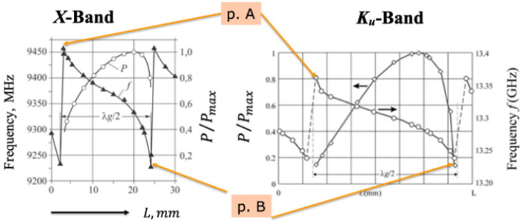
The investigation results for the double-output magnetrons in X and K
u bands are given in
Figure 16 | [12] | Shuang Qiu, Nan-nan Wang, Gennadiy I. Churyumov, A Magnetron Using an Additional External Reactive Load for Frequency Tuning: Theory Features and Experiment. IEEE Transactions on Electron Devices, Vol. 71, # 3, March 2024. pp. 2147-2152, https://doi.org/10.1109/TED.2024.3359586 |
| [13] | Gennadiy I. Churyumov, Nan-nan Wang, Volodymyr P. Gerasimov, Wei Li, Low-Voltage Kᵤ-Range Magnetron with Two Outputs of Energy: Design Features and Main Advantages. IEEE Transactions on Electron Devices. Vol. 67, # 12, December 2020. pp. 5743-5749, https://doi.org/10.1109/TED.2020.3029129 |
[12, 13]
. As shown, varying the position of the piston
within the range
, where
- reference point and
- the wavelength in a transmission line, changes the RF signal's frequency and output power. At the edges of the frequency tuning range, at points A and B, frequency jumps occur. It is important to note that the presented curves were obtained for a fixed point on the current-voltage characteristic when
. The variation of the anode voltage leads to changes in the behaviors of the dependencies mentioned above.
Figure 16. Experimental curves of frequency tuning and output power variation within the tuning ranges.
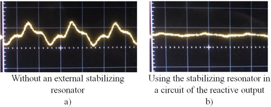
Figure 17 presents the main results of the frequency fluctuation measurement. In
Figure 17a, we have the non-stabilized initial signal, the stability of which equals 4 10
-5. After stabilizing this signal when the operating magnetron frequency
corresponds to the resonant frequency
of the stabilizing high-Q resonator, i.e.,
, we obtained the frequency stability of not more than 7 10
-7 (
Figure 17b).
Thus, applying the additional stabilizing resonator in the circuit of the passive RF output of the double-output magnetron enables more than one order of improvement in the frequency stability of the magnetron output signal. As a result, this enables using this magnetron as a primary generator in various radar systems, including coherent radars with the ability to select moving targets (Doppler radar).
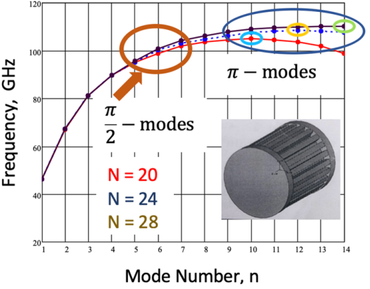
At the stage of the magnetron's design, the main attention was given to studying the "cold" dispersion characteristics of the comb structure and their dependence on its geometric sizes. The 3D simulation was carried out using the CST code. The main results of the simulation of the "cold" comb structure are shown in
Figures 18-20.
Figure 17. Oscillograms of frequency oscillations without a stabilizing resonator (a) and with one present (b).
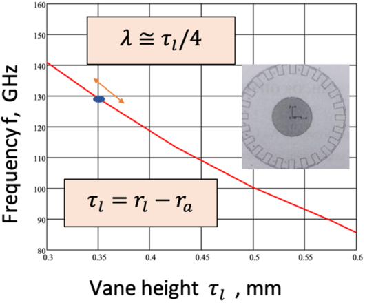
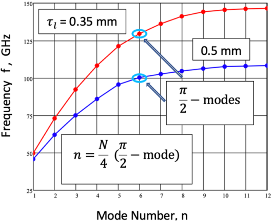
Analysis of the presented results shows that changing the number of cavities in the anode block can be done in a wide range of their values without significantly influencing the dispersion characteristics. Selecting the desired frequency of the "cold" anode block can be achieved by adjusting the height of the vanes in the anode structure, as shown in Figure 19. However, the significant decrease in the vane's height (less than 0.3 mm) has a negative influence on the unloaded Q-factor of the anode block. For example, a case when 0.35 mm corresponds to the resonant frequency of the "cold" anode block equaled 130 GHz; in addition, the anode block's unloaded Q factor is equal to 210. Thus, determining the geometrical dimensions of the comb structure requires a trade-off between the vane's height and the unloaded Q-factor of the electrodynamic structure used. It allows us to determine the resonant frequency of the operating mode of oscillation.
Figure 18. Dispersion diagram for various cavity numbers.
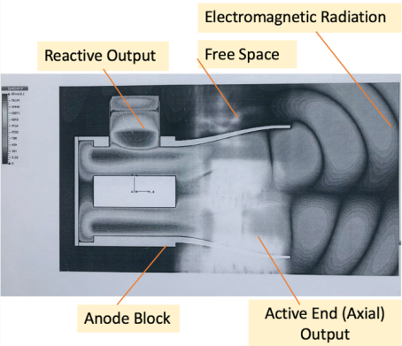
Figure 21 shows the behavior and structure of the electromagnetic wave for the
-mode of oscillation of the magnetron, the construction of which is presented in
Figure 10b. The simulation results reveal not only an electromagnetic field in the magnetron's interaction space but also a radiation process in free space through an axial RF energy output.
Figure 19. Dependence of the frequency of the anode block vs. the vane height of the comb structure.
Applying the two RF outputs in the magnetron requires additional calculations to determine the coupling magnitude between the anode block and the active and passive RF outputs, respectively. As mentioned above, for the realization of the frequency tuning and the stable operation of the double-output magnetron, it is necessary to accomplish a condition when the coupling of the passive RF output with the anode block is stronger than the analogous coupling for the active RF output, i.e., in this case
Figure 20. Dispersion diagrams for different values of the vane height.
Figure 21. Distribution of the electromagnetic field of the operating oscillation mode in the double-output magnetron with diffraction RF output.
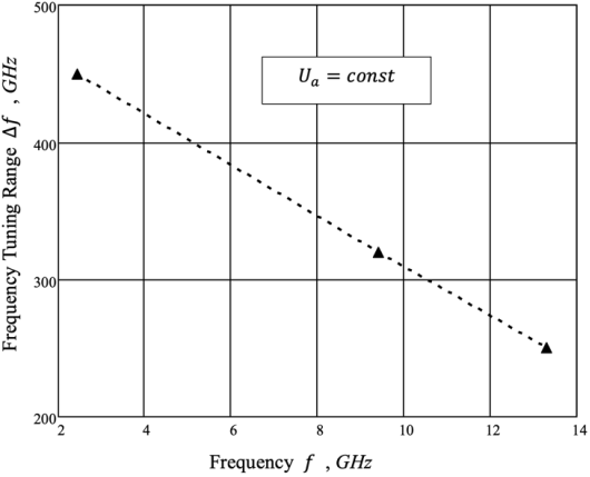
The predictable maximum frequency tuning range for the double-output oven magnetron is shown in
Figure 22. This result is based on an arithmetic extrapolation of the experimental data for the X and Ku-band double-output magnetrons. As can be seen, the maximum frequency tuning range for a double-output oven magnetron is approximately 450 MHz.
Figure 22. A curve frequency tuning range vs. frequency for the double-output oven magnetron.